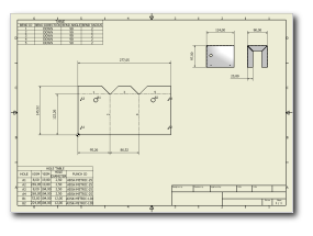
In this tutorial, you learned a basic workflow for creating a sheet metal part and placing sheet metal annotations on a flat pattern drawing. Some key points of this exercise include:
- Working within the context of an assembly, you were able to use assembly geometry to define key design aspects of your sheet metal part.
- Sheet metal features are often created on one side or the other of a selection to take into account the material thickness or bend radius.
- Sheet metal Punch iFeatures simplify the creation of simple and complex cut (and formed) features on your model. Punch iFeatures carry attribution that can be recovered in a Punch table on your drawings.
- Bends created by features display a bend centerline and bend extents on the flat pattern. These bends can be easily identified in a Bend table on your drawing that contains important manufacturing attributes.
- The flat pattern of your folded model is easily created and provides an accurate representation of the flattened bend zones between adjacent features. The size of these flattened bend zones are determined by the Unfold Rule defined within the active Sheet Metal Rule used when you begin a new sheet metal model from a template.
What Next? - As a next step, continue to explore sheet metal functionality by completing the Sheet Metal Parts 2 tutorial.