- On the ribbon, click
Annotate tab
 Table panel
 Hole View
(use the down arrow to the right of Hole to display Hole View).
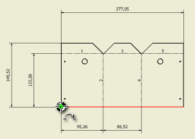
- Move your cursor over the view of the flat pattern until you see the dotted red view boundary highlight, and click to select the view.
- Move the datum target cursor along the lower edge of the flat pattern, until you reach the left-most corner and the “point on” constraint is indicated.
- Click to select this point as the datum for dimensioning the punched holes.
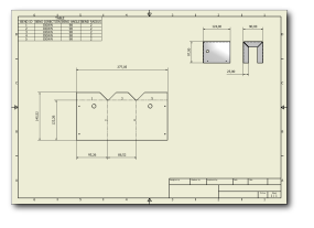
- Move the displayed outline of the table to align it with the lower-left corner of the drawing boarder. When the “point on” constraint is indicated, click to place the table.
- Right-mouse click over the table, and select Edit Hole Table from the context menu to display the Edit Hole Table: View Type dialog box.
- Click Column Chooser on the Formatting tab of the dialog box to display the Hole Table Column Chooser dialog box.
- In this dialog box, select Description from the list of Selected Properties, and click Remove.
- Select HOLE DIAMETER in the list of Available Properties, and click Add.
- Select PUNCH ID in the list of Available Properties, and click Add.
- Click OK to accept the new column arrangement and close the Hole Table Column Chooser dialog box.
- Click OK in the Edit Hole Table: View Type dialog box to update the table using the new column arrangement and close the dialog box.
- Save the drawing of the guard flat pattern.
Previous | Next

 Table panel
 Hole View
(use the down arrow to the right of Hole to display Hole View).
