In this section, you define the workpieces, patching and runoff surfaces, and core and cavity for the Exp-Mobile Top and Exp-Mobile Bottom components.
Each of these commands must be completed on both the Exp-Mobile Top and Exp-Mobile Bottom components. When a command is completed on one of these models, its other patterned instance automatically updates.
Defining the Exp-Mobile Top component
- In the Mold Design browser, double-click the Exp-Mobile Top node to activate it.
- On the ribbon, click Core/Cavity tab > Parting Design panel > Define Workpiece Setting
 .
. - Maintain the default Rectangular Workpiece Type and change the following:
- X_total = 100 mm
- Z_total = 60 mm
- Click OK.
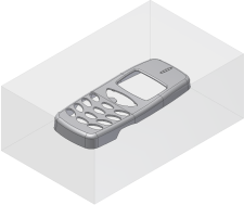
- Click OK on the File Naming dialog box to accept the defaults. The workpiece appears as shown in the following image.
- Click Create Patching Surface
 .
. - Click Auto Detect
 on the dialog box. The system automatically detects 19 patches and lists them by name in the Create Patching Surface dialog box. Some of the openings may not be successfully patched until you perform the next step.
 - To achieve higher quality surfaces in the final product, click All Lower
 to switch the patching surfaces to the lower edges of the model . Note: Different models have been used in the General Mold Workflow tutorial and this tutorial, so the patching surface procedures vary. It is important to remember that the Create Patching Surface command is a starting point for patch surface creation. Reviewing the surfaces that are created and using manual patching techniques where necessary is recommended.
Refer to the tutorial sectionDefining the parting surface in the General Mold Workflow tutorial to see an animation that shows creating patching surfaces manually.
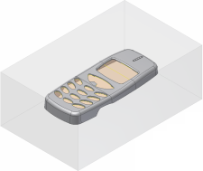
- Click OK. The surfaces are created as shown in the following image.
- Click Create Runoff Surface
 .
. - Click Auto Detect
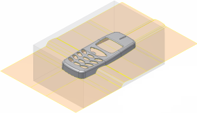
 on the dialog box and then click OK to accept the default runoff surface. The surface is shown in the following image.
- Click Generate Core and Cavity
 .
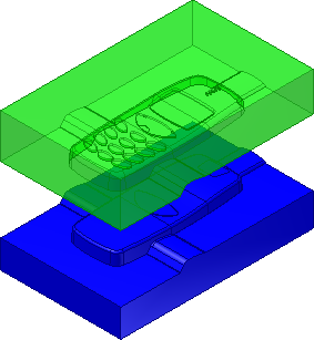
. - Click Preview/Diagnose. Change the Body Separation value to 100. The preview changes to the specified value as shown in the following image.
- Click the Parting Diagnostics tab. No significant problems are detected. Click OK to accept.
- Click OK on the File Naming dialog box to accept the defaults.
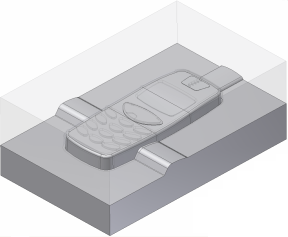
- The core and cavity is automatically generated, as shown in the following image.
Defining the Exp-Mobile Bottom component
- In the Mold Design browser, double-click the Exp-Mobile Bottom node to activate it.
- On the ribbon, click Core/Cavity tab > Parting Design panel > Define Workpiece Setting
 .
. - Maintain the default Rectangular Workpiece Type and change the following:
- X_total = 100 mm
- Z_total = 60 mm
- Click OK.
- Click OK on the File Naming dialog box to accept the defaults.
- Click Create Patching Surface
 .
. - Click Auto Detect
 on the dialog box. The system automatically detects one patch.
 - Click OK.
- Click Create Runoff Surface
 .
. - Click Auto Detect
 on the dialog box and then click OK to accept the default runoff surface.
 - Click Generate Core and Cavity
 .
. - Click Preview/Diagnose to preview the core and cavity.
- Click the Parting Diagnostics tab to check for errors.
- Click OK on the Generate Core and Cavity dialog box.
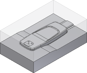
- Click OK on the File Naming dialog box to accept the defaults. The core and cavity are automatically generated, as shown in the following image.
- On the Exit panel, click Finish Core/Cavity
 .
.