In this topic, you use the Pattern command to design a multi-cavity mold in which the plastic parts are laid out in a rectangular pattern.
- On the ribbon, click Mold Layout tab > Mold Layout panel > Pattern
 .
. - Ensure that the Plastic Part
 selector option is active.
 - Select the Exp-Mobile Top.ipt part in the graphics window. Remain in the Rectangular tab to generate a rectangular pattern of the components.
- In the Y Direction, enter the following:
- Number of instances = 2 ul
- Offset = 180 mm
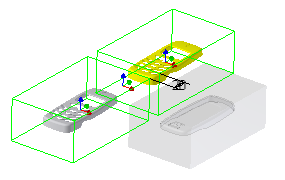
The mold assembly appears, as shown in the following image.

- Click X Balance
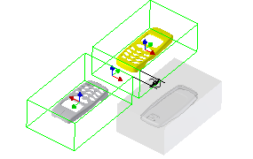
 . The orientation of the mold components changes, as shown in the following image.
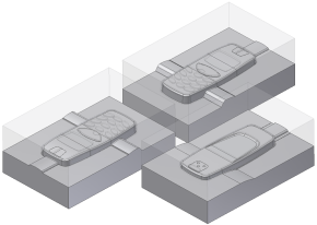
- Select the Variable tab and then select the Inherit from the last pattern option to maintain the rectangular pattern that was previously defined. Two elements representing the two instances are listed.
- Modify the offset values to reposition the mold assembly coordinate to the center of the layout. In the X Offset, enter the following:
- Element 1 = -60 mm
- Element 2 = -60 mm
- Expand the dialog box to expose the More options. Notice that both components are designated as unique files. This means that each component can have unique features instead of being identical copies.
- Click OK.
- Click OK on the File Naming dialog box to accept the defaults and complete the pattern.

- Click Pattern
 .
. - Select the Exp-Mobile Bottom.ipt part in the graphics window. Remain in the Rectangular tab.
- In the Y Direction, enter the following:
- Number of instances = 2 ul
- Offset = 180 mm
- To change the orientation of the mold components, click X Balance
 .
. - Select the Variable tab and then select the Inherit from the last pattern option to maintain the rectangular pattern that was previously defined. Two elements representing the two instances are listed. Notice that these files are also designated as unique files in the More section of the dialog box.
- Modify the offset values to reposition the mold assembly coordinate to the center of the layout. In the X Offset, enter the following:
- Element 1 = -60 mm
- Element 2 = -60 mm
- Click OK.
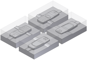
- Click OK on the File Naming dialog box to accept the defaults and complete the pattern. The mold assembly appears as shown in the following image.
