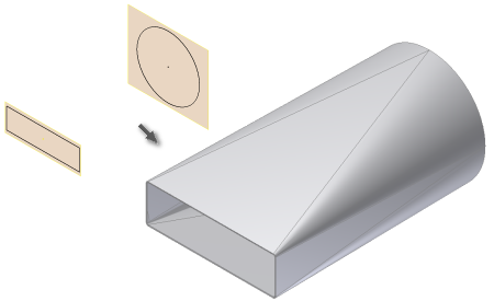
Certain design situations call for smooth, die formed transitional shapes. Autodesk Inventor supports a die formed output option that requires the selection of two sketch profiles as input.
- On the ribbon, click
Sheet Metal tab
 Create panel
 Lofted Flange
. The Lofted Flange dialog box is displayed.
 - In the graphics window, click the visible sketch geometry which defines the first profile of your Lofted Flange.
- In the graphics window, click the visible sketch geometry which defines the second profile of your Lofted Flange. If the Enable/Disable feature preview is checked on the dialog box, the Lofted Flange result is previewed.
- On the Lofted Flange dialog box, click the Die Formed output option on the Shape tab. If Enable/Disable Feature Preview is checked on the dialog box, the smooth, die formed Lofted Flange results is previewed.
- On the Shape tab of the Lofted Flange dialog box, optionally specify a Bend Radius value that differs from the Bend Radius defined in the active Sheet Metal Rule.
- On the Unfold Options tab, optionally specify an Unfold Rule that differs from the Unfold Rule defined in the active Sheet Metal Rule.
- Click OK to create the Lofted Flange and close the dialog box.
| Notes: |
|