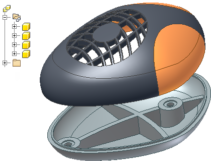
Creating a design with complex blends and curves that extend across multiple parts presents unique challenges. Starting with the finished exterior shape and working out individual part details as you go is a more natural workflow to many designers. The technique of designing the finished shape and extracting components is sometimes called a top down design method.
A multi-body part is a top down workflow which allows you to create and position multiple bodies within a single part document. This technique is especially useful for designing plastic parts. A top down workflow eliminates the need for complex file relationships and projecting edges between parts. You can control visibility, assign a different appearance, and calculate the mass for each solid body. When you complete the design, you can export the individual solid bodies as part files directly into an assembly.
The advantages of using a multi-body part in a complex design are:
- Significantly reduces design time.
- The entire design resides in one document.
- All editing takes place in a single file.
- No up-front planning for file structure is required.
- All generated part files are associative with the master design.
How do I create a multi-body part?
![]() Creating a multi-body part is an efficient top down design workflow. You use common modeling commands to create a new body in the context of other bodies. Use sketch-based modeling commands like Extrude, Revolve, Loft, Sweep, and Coil to create a new body by selecting the New Solid option in the dialog box.
Creating a multi-body part is an efficient top down design workflow. You use common modeling commands to create a new body in the context of other bodies. Use sketch-based modeling commands like Extrude, Revolve, Loft, Sweep, and Coil to create a new body by selecting the New Solid option in the dialog box.
Use the Split command with the Split Solid option to create separate bodies in a part file. You can use workplanes, 2D sketches, and surfaces to define the split boundary. Use surfaces to define complex split boundaries.
Use the Derive command to import components into a part file as new bodies or to use as toolbodies for a cut, join, or intersect operation.
Can I move or merge bodies?
Use the Move Bodies command to position a body within the part document. Use the Combine command and select one or more solids to use as toolbodies to perform a join, cut, or intersect operation on a selected body.
What happens if I create a multi-body part by mistake?
If you accidentally create a multi-body part, you can edit the feature to change the solution to a Join, Cut, or Intersect operation. An undo operation also reverses the step. If it is too late to perform an edit or undo, you can use the Combine command with the Join option to merge the bodies. You can also delete the operation, such as a split, that created the new body. Features that were created on the new body are also deleted.
What happens if I create a new feature instead of a new body by mistake?
You can edit any sketch-based feature after creation and change the solution to create a new body.
What is in the Bodies folder?
A body is an independent collection of features contained within the part file. All new bodies are added to the appropriate folder in the browser at the time of creation. You can control the visibility and appearance of solid and surface bodies by selecting a body and choosing Properties in the context menu.
Expand a body in the folder to list the features that are applied to each body. Different bodies can share the same feature such as a fillet, chamfer, or hole.

An Application Option in the Modeling tab of Document Settings allows you to specify the default naming scheme prefix for new solid or surface bodies. The default body names are Solid for solid bodies and Srf for surface bodies.
How do I control body visibility?
- Select a body using one of the following methods:
- Set the selection filter to Select Bodies and pick one or more bodies in the graphics screen.
- Expand the solid bodies folder and select one or more bodies in the browser.
- After you select one or more bodies, use one of the following options in the context menu:
- Visibility
- Show All
- Hide Others
Use Show All to unhide all solids in a part file.
Use Hide Others to retain the selected solids, and to turn off the visibility for all unselected solids.