Edit the part in place to add individual pins and a placeholder reference designator to a part. The connectors are already placed in the assembly.
Each pin name within the selected part is unique. The pin name specified is also the name of the special work point feature listed in the browser.
Add pins in the assembly
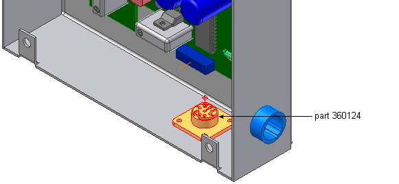
- In the browser, pause the cursor over the part named 360124.
The part highlights in the graphics window so that you can see the part to edit.

- In the browser, double-click the part name to edit the part.
- In the Model browser, delete work points 1 through 9. You re-create these points in the next steps.
-
 On the ribbon, click
3D Model tab
 Harness panel
 Pin
.
Pin
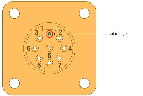
. - Rotate and zoom the view to see the part as shown in the following image. Turn visibility off for any parts obstructing your view.
- Click the circular edge shown to select the center point.

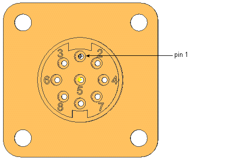
- On the Pin Name dialog box, use the default pin name of 1 and click
 . The work point representing the pin is added for pin 1.
- Define a pin for hole 2:
- Select the circular edge.
- Accept the Pin Name of 2.
- Click
 .
.
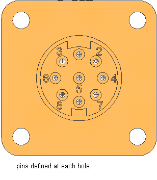
- Repeat the steps to define a pin at each labeled hole and hole 9 located between holes 7 and 8. Name the pins to match their number label. For example, enter a Pin Name of 3 for the hole labeled as 3, and so on.

- To exit Place Pin mode, right-click, and then select Done.