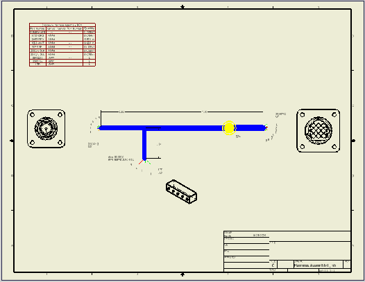
Place two connector views using default display settings and then override the default display settings for the other connector.
-
 In the drawing view, click
Nailboard tab
 Create panel
 Place Connector Views
.
 - In the connector list, clear the check box for LTP:1, and then click OK.
The selected connectors are placed using the default display settings.

- Click Place Connector Views again.
- Under Orientation, click the arrow to select ISO Top Right from the list, and then click OK.

- Save your work.
To change the views after placement, right click the view to change, and select Edit View or Edit View Orientation. To delete a connector base view, right-click the view and select Delete.