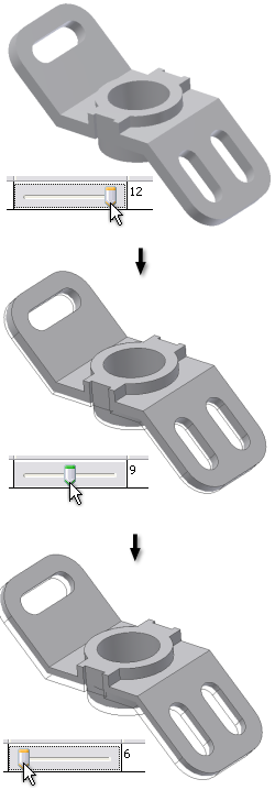
We will produce a range of geometric configurations involving the thickness of the model to facilitate weight optimization. Adding parameters to the parametric table is required.
Add parameters to the parametric table
- In the Manage panel, click Parametric Table.
- In the browser, right-click the part node just below the Simulation (Parametric) node, and click Show Parameters.
- In the Select Parameters dialog box, check the box to the left of the parameter named d2, 12 mm.
- Click OK.
After identifying the parameter we want to use, we must define a range for the parameter and generate the corresponding geometric configurations.
Define parameter range
- In the Values cell for Extrusion1 d2, enter the range 6-12. The values must be in ascending order.
- Press Enter to accept the values. When you click inside the Value field, the value now says 6-12:3. This indicates that there are now three values in the range. These are equally divided between the first and last number, hence that values are 6, 9, and 12.Note: The number after the colon specifies the additional configurations desired, excluding the base configuration. The base is 12 mm, and the two additional configurations are 6 mm and 9 mm.
Once the parameter range is specified, we can generate the various configurations based on the range values.
Generate configurations
- Right-click the table parameter row, and select Generate All Configurations. The model generation process is started.
- After the model regeneration is completed, move the slider to see the different shapes created.

We are not finished with the Parametric Table yet, so do not close it.