In this tutorial, you learned how to:
- Import layer-specific DWG data into an Autodesk Inventor sketch. Then create an Autodesk Inventor solid model of the ACAD drawing views using the actual DWG geometry and dimensional values.
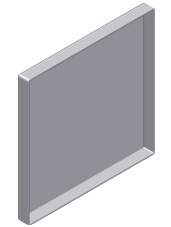
- Add round and shell features to an extrusion.
- Use and refer to the imported DWG data to determine feature dimensions.
- Use the Autodesk InventorOrbit command to make the selection of geometry easier during feature modeling.
- Use Autodesk Inventor marking and context menus to access commands that apply to the current selection.
- Use the Visibility option on browser objects to ease your design process.

The next tutorial in this set demonstrates the common workflow of how to create a part in the context of an assembly. As with the two previous tutorials, you also import and use DWG data to define the part.