This type of part would be manufactured using sheet metal. In this tutorial, you use the Shell command to create the uniform thickness of the sheet metal in a regular Autodesk Inventor part. The steps you would use to model this type of part using the Autodesk Inventor Sheet Metal commands are covered in another tutorial.
- On the ribbon, click
3D Model tab
 Modify panel
 Shell
Shell
 .
. - Use Orbit to approximate the view shown in the following image. The exact orientation is not important.
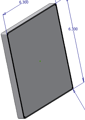
- Use the Shell command to hollow out the model while maintaining a specified wall thickness. You can remove faces of the model that will be open after completing the command.
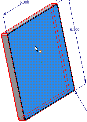
- Select the face with the sketch.
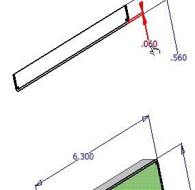
- Using the dimension-referencing technique you learned previously, highlight the default value in the Thickness field of the Shell dialog box, and select the dimension value .060 located in the top view of the sketch geometry to set the material thickness.
- Click OK to create the shell and exit the command.
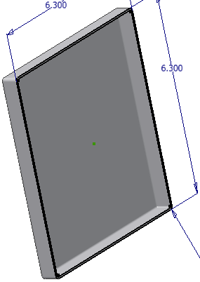
Notice that because you created the round before the shell, the program creates the inner fillet automatically as part of the shell operation.
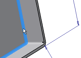
- In the Model browser, right-click the Sketch1 browser node and remove the check mark next to Visibility to turn off the display of the sketch.
- Save the part, using cover_panel for the file name.
- Close the part.