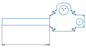
After you open the part file, note the presence of one sketch, Sketch1, in the Model browser. Click Sketch1 and you see all geometry in the graphics window highlighted. You can use one 2D sketch to create all your geometry then group the appropriate geometry into sketch blocks.
- Use navigation commands, such as View Face and Zoom Window, to position the sketch geometry in the graphics window as shown.
- Double-click Sketch1 in the Model browser.
- Window-select the lowermost geometry, and click Create Block
 in the Layout Panel on the Sketch tab.
 Note: You can pre-select geometry and activate the Create Block command, or you can activate the command and select geometry.
 - For Block Name, enter Worm Gear Assy. You can also define the insert point and add a description. The insert point is where the sketch block is attached to the cursor when block instances are placed.
- Click OK. The sketch block is created.
- Expand Sketch1 in the Model browser. Pause the cursor over the sketch block instance
 , Worm Gear Assy:1. The associated sketch geometry highlights in the graphics window.
 Create Block creates a sketch block definition in the Blocks folder
 and replaces the original 2D sketch geometry with an instance of the block. Expand the Blocks folder to view the Worm Gear Assy block definition node.
 - You can create multiple sketch blocks without closing the Create Block dialog box. Click Create Block on the Sketch tab, and select the geometry shown. Enter Connecting Rod as the Name, and click Apply. The block is created, and the dialog box awaits selection of geometry for the next block.

- Select the geometry shown, and create the Link Plate sketch block.

- Select the geometry shown, and create the Pivot Plate sketch block.

- Exit the sketch, and save your file.