In this section, you use standard assembly constraints to constrain the insert. The location of the placement will be a mirror image of the insert that was created for you.
- On the Model browser, double-click the node labeled Mold_Top_Top_PZ:1 to activate it.
- On the Model browser, expand the Mold Top_Top_MP:1 node to review the constraints as they are added.
- On the ribbon, click Assemble tab > Position panel > Constrain
 .
. - On the Place Constraint dialog box, ensure the Mate type is selected
 .
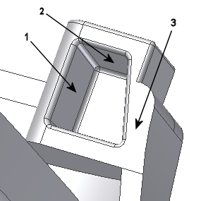
. - Select the surface labeled 1 in the following image as the First Selection
 reference. This surface is on the moldable part component.
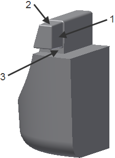
- Select the surface labeled 1 in the following image as the Second Selection
 reference. This surface is on the placed insert component.
- Click Apply.
Note: Consider using the  command on the Position panel to drag the component away from its currently constrained location. You can select the reference surfaces more easily.
- Continue to constrain the insert by using mate constraints:
- Mate the surfaces labeled 2 in the two previous images.
- Mate the surfaces labeled 3 in the two previous images.
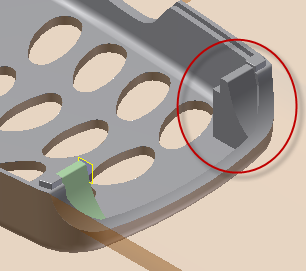
The fully constrained insert appears as shown in the following image.

- When the component is fully constrained, click Cancel on the Place Constraint dialog box to close the dialog box.
- To exit the Assembly environment, click Assemble tab > Return panel > Return
 .
. - On the ribbon, click Core/Cavity tab > Exit panel > Finish Core/Cavity
 .
. - On the Mold Design browser, expand the Representations > View nodes, and double-click View1. Note: You can also set the view on the ribbon view representation drop-down.
- On the keyboard, press F6 to return to the Home View. The model appears as shown in the following image.

- On the Quick Access toolbar, click Save to save the assembly.