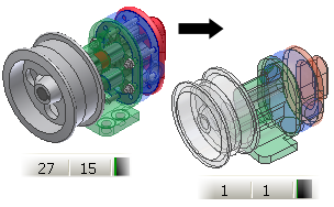
The Shrinkwrap command creates either a derived solid or a derived surface composite from an assembly. Shrinkwrap uses the active View or Level of Detail representation of the assembly. Components that are not visible or are suppressed are not included in the shrinkwrap part. For example, activate a View or LOD representation that contains no hardware or internal parts to perform fewer calculations.
Update the Mass Properties of the source assembly before you create the shrinkwrap part to copy the mass properties to the shrinkwrap part.
- (Optional) Calculate the Mass Properties of the assembly to include them in the substitute.
- (Optional) Create a Design View or LOD representation that contains only the required components.
- (Optional) Activate the representation.
- Start the Shrinkwrap command.
- In the Create Shrinkwrap Part dialog box, specify the new component name, template file, file location, and BOM structure.
- Click OK.
- If the mass properties are up to date and the active LOD is not the Master LOD, you are prompted to copy the Mass Properties of the Master or the active LOD before proceeding.
- The Assembly Shrinkwrap Options dialog box opens. In the Style area, select one of the following options:
- Select
 Single solid body merging out seams between planar faces to create a solid with no visible edges between planar faces.
 - Select
 Solid body keep seams between planar faces to create a single solid with visible edges between planar faces.
 - Select
 Maintain each solid as a solid body to create a multi-body part that contains a unique body for each part in the assembly.
 - Select
 Single composite feature (default selection) to create a surface composite body. This option offers the fastest calculation time and creates the smallest file on disk.
Note: It is possible to produce gaps when small faces are removed. If gaps are present, the result is a non-manifold body. - Select
- Select Remove parts by size and adjust settings if necessary. The ratio indicates the bounding box of the part to the bounding box of the assembly.
- Adjust the settings in Hole patching if necessary. Holes do not need to be round to be included. The All setting removes all holes that do not cross surface boundaries.
- Adjust the Include other objects settings if necessary.
- Select Break link if necessary to disable updates permanently and remove associativity between the parent assembly and the shrinkwrap part.
- Select Remove all internal voids to fill all internal void shells in the shrinkwrap solid body part.
- Select Reduced Memory Mode to create the smallest file on disk. It is selected by default. Enable to reduce the browser data stored in the shrinkwrap part.
- Select Create independent bodies on failed Boolean to create a multi-body part when a Boolean operation fails on one of the single solid body style options.
- Click OK to finish the command and create the substitute.