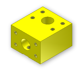
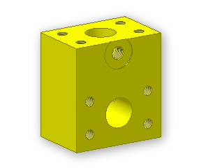
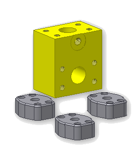
The block is the first part placed into the assembly.
- Close any open Autodesk Inventor files, and make sure that iLogic 2012 Tutorials is set as the active project.
- Create a new assembly using the Standard.iam template.
-
 On the ribbon, click
Assembly tab
 Component panel
 Place
.
 - In the Open dialog box, double-click manifold_block.ipt. It is the part file you created in the Manifold Block Part tutorial.
A grounded occurrence of the component is placed in the assembly, and the part origin is aligned with the assembly origin.

- To cancel placement of further copies of the component, right-click the graphics window and select Done.
- Use Orbit to orient the manifold block as shown.

In addition to the block, this assembly includes three union caps and three sets of screws to attach the caps.
- Select the Place command again, and double-click union_cap.ipt.
A copy of the component becomes attached to the mouse pointer. and the Place Standard iPart dialog box is displayed.
- Click the Table tab, and select iPart member Union-01 (Part Number U-050).
- Click in the graphics window to place a copy of the union cap near the manifold block. Click two more times to add a total of three union caps, then click Dismiss to close the dialog box.

Now you can add the screw components.
- Select the Place command again, and double-click Screw.ipt.
- In the Place Standard iPart dialog box, select iPart member Screw-01. Place four Screws in the graphics window, and then click Dismiss to close the dialog box.

- Save your assembly as my_manifold_block.iam.
You are ready to begin assembling the components and establishing their relationships.