After selecting the axis of revolution, the in-canvas display appears in the graphics window. Take a moment to examine the various elements of the in-canvas display.
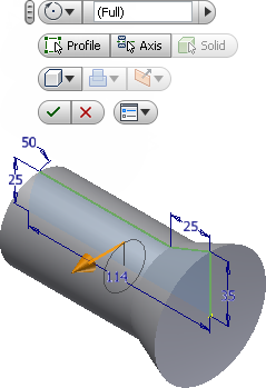
The value input box reports that a full 360° revolution will be performed around the sketch axis you selected. It is the default condition for the Revolve command and the graphical preview on your display screen reflects that. However, you can enter any angular value in the value input box to create a revolution other than a full 360°.
As an alternative to entering an explicit angular value in the value input box, you can also click the gold rotation arrow manipulator. Then dynamically drag the sketch profile around the axis of revolution.
- Try it now. Click the rotation arrow manipulator and drag the profile around the axis. First drag in one direction, and then try dragging in the opposite direction. As you drag the rotation arrow, observe the changing angular values displaying in the value input box. Note also that the graphical preview updates in real time to show the results of the Revolve operation.
- When you are finished experimenting with dynamic drag, direct your attention to the Revolve mini-toolbar in the in-canvas display.
- Starting at the upper-left, let us examine each of the buttons.
- The grip button
 lets you easily move the mini-toolbar to a different screen location.
 - The fly-out arrow on the Extents button
 offers several termination options:
 - Angle lets you revolve the sketch profile around the axis at any angle.
- To next face/body lets you revolve to an existing face or body of a multi-body part.
- To selected face/plane lets you revolve to an existing part face, work plane, or work point.
- Between two faces/planes lets you select beginning and ending faces or work planes on which to terminate the revolution.
- Full performs a full 360° of revolution around the sketch axis.
- Click the Profile button
 and then select the sketch to revolve. (Remember that the very first sketch in a new part file is selected automatically.)
 - Click the Axis button
 and then select the axis about which to revolve the profile.
 - The Solid button
 selects the participating solid body in a multi-body part.
 - The Solid output button
 lets you revolve a profile into a solid or a surface object.
 - The Join button
 adds the volume created by the revolved feature to another feature or body. We will explore the Cut and Intersect options a bit later in this tutorial.
 - The fly-out arrow on the Direction button
 displays the direction options available:
 - Direction 1 revolves the sketch profile in the positive direction (towards you).
- Direction 2 revolves the sketch profile in the negative direction (away from you).
- Symmetric revolves the sketch profile in both directions with equal angular values.
- Asymmetric revolves the sketch profile in both directions with different angular values.
- Click the Ok button
 to finish the Revolve command and complete the revolution.
 - The Cancel button
 cancels the Revolve command. No revolution is performed.
 - The Mini-Toolbar Options button
 offers two options. You can pin the mini-toolbar so that it remains stationary in the graphics window and/or use the Auto Fade option to enable or disable the mini-toolbar display.
Tip: Work planes, work points, and work axes are called work features in Inventor. They are abstract construction geometry used when regular part geometry is insufficient for creating and positioning new features. You create an offset work plane later in this tutorial. - The grip button
- Now, select the Full option in the Extents button flyout and click the green Ok button to complete the Revolve command.
- Observe that the Revolution1 feature was added to the Model browser. Click the + button to the left of the feature name to expand the item. The feature has one child - the sketch from which it was created.
- Move your cursor over both the Revolution1 feature name and Sketch1 in the browser. The corresponding items highlight in the graphics window as you do so.
Tip: Moving your cursor over the various features in the Model browser is a handy method for locating a specific feature or features in a complex part model or assembly.