Every drawing contains text and annotation. This text may be attached to drawing geometry with an arrow leader or contained within a specific area of a title block or revision table. It can be a lengthy set of notes.
To place text:
- On the ribbon, click
Annotate tab
 Text panel
 Text
Text
 .
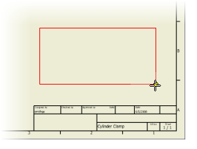
. - Placing text on a drawing requires you to specify a location and an approximate initial size of the area occupied by the block of text. Move your cursor to the empty area above the title block. Click and drag a rectangle approximately as shown in the following image:
 Note: For smaller amounts of text, your initial rectangle can be smaller. The size of the text boundary can be adjusted at any time after placement so getting it exactly correct is not critical.
When you release the mouse button, the Format Text dialog box displays. In addition to some text formatting options, this dialog box contains a large text entry field located along the bottom of the dialog box. For many general notes, you can accept the text formatting defaults (which are specified by the active style for your drawing).
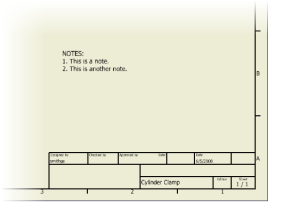
- Enter text in the text entry field. Type NOTES:, then press Enter and continue to type 1. This is a note. Press Enter again and continue to type 2. This is another note.
- Click OK to place the text you typed in the text entry field on the drawing sheet, within the area specified by your rectangle.

- Select another command, or click Esc to terminate the Text command.
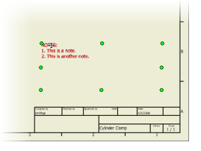
- Click the placed text.

The text highlights and displays edit handles (green-filled circles). You can drag the entire text block to a new location or move your cursor over one of the eight edit handles to resize the text block boundaries.
- With the text selected, right-click and select Edit Text from the context menu. The Format Text dialog box opens with the selected text in the entry field. You can highlight individual words and apply formatting (bold, italic, underline) or change font or size.
- Click Save to save the Cylinder Clamp drawing. Note: After clicking Save, you may be presented with the Save dialog box prompting you with: Do you want to save changes to ‘Cylinder Clamp.idw’ and its dependents? You can click the Yes to All button to save all the files associated with the assembly, or click No to All if you wish to save none. Click the OK button to save only the files changed in this exercise and close the dialog box.
Congratulations! You have completed the Drawings tutorial. A brief summary follows.