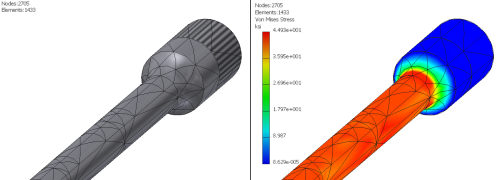
For occasions where you see a stress concentration, you will want to consider setting the mesh a little finer. The Mesh Settings specify the mesh parameters for use in the simulation. Mesh parameters apply to all components and model features.
Access the Mesh Settings:
- On the ribbon, click
Stress Analysis tab
 Mesh panel
 Mesh Settings
. Alternatively, right-click the Mesh browser node and click Mesh Settings.
 - Specify the desired settings in the Mesh Settings dialog box.
Setting Use Default Recommended unless otherwise required Average Element Size Specifies the element size relative to the model size. 0.1 Between 0.1 and 0.05 Minimum Element Size Allows for automatic refinement in small areas. The value is relative to the Average Size. 0.2 Between 0.1 and 0.2 Grading Factor Effects the uniformity of the mesh transition between fine and coarse mesh. Specifies the maximum edge length ratio between adjacent element edges. For example, a setting of 1.5 limits an elements edge length to 1.5 times the edge length of the adjacent element. 1.5 Between 1.5 and 3.0 Maximum Turn Angle Effects the number of elements on curved surfaces. The smaller the angle, the greater the number of mesh elements on a curve. 60 deg. Between 30 and 60 deg. - Click OK to apply the changes.