Define a harness segment between two circular connectors (360124:1 and 360575:1) and around the PCB board in the enclosure. Adjust the offset while you work.
- Open Enclosure_Assembly.iam from the Cable & Harness subfolder. It is the same assembly you used in the previous tutorial.
- In the browser, double-click Harness Assembly1 to activate it for editing.
-
 On the ribbon, click
Cable and Harness tab
 Create panel
 Create Segment
.
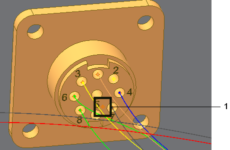
 - Rotate and zoom in to component 360124 then select the work point shown in the following image.

A segment work point is created at the selected point.
- Move the cursor over the bottom of the enclosure until the tooltip and offset symbol appear. The tooltip displays the offset value as 0.100 in, and the symbol shows the actual offset distance as a guide for your selections.
- Before you select the second point, increase the offset to prepare for a branch in the harness. To increase the offset, right-click, select Edit Offset from the context menu, and then enter 0.270.
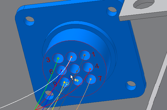
- For the second point orient and zoom the view as shown, and then select a point based on the bottom of the enclosure.
As you make your selections, the system displays a straight line from the selected point to the current cursor position.

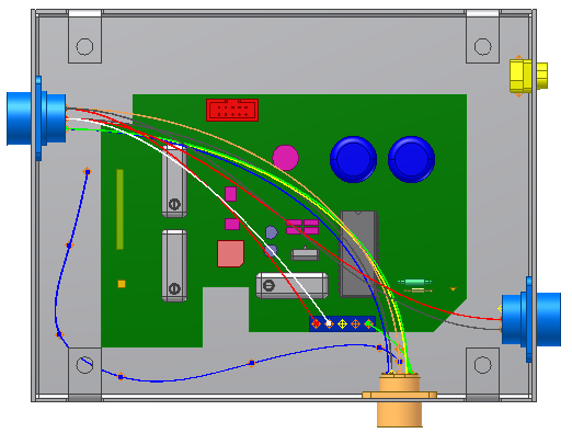
- Continue selecting points around the printed circuit board (PCB) and toward the other connector to create the segment shape.
The following image shows several additional point selections. Exact placement of the work points is not important. You can adjust the work points after the segment is complete.

- Right-click, select Edit Offset, and then enter 0.200 to change the offset value for the last point.
- Click to select the point as shown in the illustration.

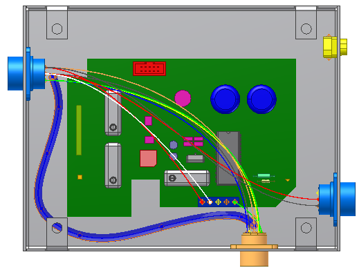
- Right-click and select Finish to complete the segment.Note: If an error message is displayed and the sweep cannot be generated, adjust the work points in areas of highest curvature to reduce the curve.
The system generates the segment, as shown in the following illustration.

- Save the harness assembly.