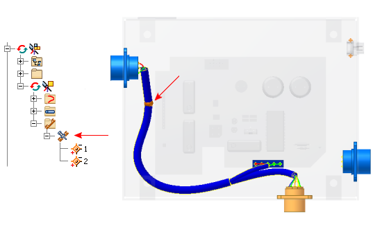
In Cable and Harness, splices are a virtual representation of the splice location and the wires that join to make a path for electricity to flow.
Each splice contains two pins. It is created with a default size, and is offset a specified distance from selected face geometry. It can also be associated to selected geometry. Splices are typically placed on segments with little or no bending at the splice location. The embedded length is set on splices or splice pins.

A default splice is provided in the Cable and Harness Library. You cannot change settings on the default splice, but you can define your own splice, and then set different defaults as needed. To change settings on splice occurrences, right-click, select Harness properties from the context menu and change settings on the Splice Properties dialog box.
Once a splice is positioned in the harness assembly, it can be included in standard assembly drawings and nailboard drawings. In the nailboard drawing, the splice is represented with a unique color and symbol. Splice information is also included in reports and when saving data to the XML format.
| For information | |
|---|---|
| Help topic | Work with splices |
| Tutorial | Routed Systems - Create Splice |