Next, you create the three tubes that form one side of the frame. Two of the tubes are identical, so creating them as separate parts might not be the best solution for a parts list or BOM.
You use a subassembly in a slight variation of the preceding workflows. In this workflow:
- First, you create a subassembly in-place in the assembly. In the subassembly, you first create a frame layout from a derived sketch. This sketch is not used to create solid geometry.
- Next, create the two different tube parts in the subassembly, using the same skeleton technique you used previously.
- Finally, place a second instance of one frame tube, and assemble it using assembly constraints. The second instance of the tube is constrained to the derived sketch in the layout part.
Note: You incorporate the vertical leg in the subassembly later in this topic.
- On the ribbon, click
Assemble tab
 Component panel
 Create
. In the Create In-Place Component dialog box:
Create
. In the Create In-Place Component dialog box:- Enter Frame as the assembly name.
- Base the assembly on the Standard(mm).iam template.
- Click OK.
- Click the assembly origin XY Plane in the Model browser to align the subassembly to the top-level assembly. The Frame subassembly is the active component in the assembly.
- Click
Assemble tab
 Component panel
 Create
. In the Create In-Place Component dialog box:
Create
. In the Create In-Place Component dialog box:- Enter FrameLayout as the part name.
- Base the part on the Standard(mm).ipt template.
- Click OK.
- Align the part to the XY plane of the Frame subassembly origin. Because it is the first part in the subassembly, it is grounded and aligned to the subassembly origin.
- Exit the sketch in the new part, and then delete Sketch1 to tidy up the Model browser.
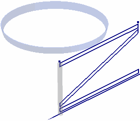
- Derive SkeletonBase.ipt into the new part. Exclude all geometry other than the FRAME SKETCH sketch. Your part should match the following image. Note: Other geometry may be visible in your graphics window. You can navigate the Model browser and turn visibility off for other geometry to replicate the image as shown. However, this action is not necessary to continue the tutorial.

- Click Return on the Quick Access toolbar to return to the subassembly environment. The FrameLayout part should be grounded.
- Click
Assemble tab
 Component panel
 Create
. In the Create In-Place Component dialog box:
Create
. In the Create In-Place Component dialog box:- Enter HorTube as the part name.
- Base the part on the Standard(mm).ipt template.
- Click OK.
- Expand the Origin folder under Frame.iam in the Model browser. Click the XY Plane node. It aligns the part origin to the subassembly origin.
- Exit the sketch in the new part, and then delete Sketch1 to tidy up the Model browser.
- Derive SkeletonBase.ipt into the new part:
- Exclude all sketches other than the FRAME SKETCH sketch.
- Exclude Work Geometry and Surface Bodies from the derived part.
- Include Parameters. You use one of the parameters from the skeleton part to control the extrusion distance of the base feature in the new part.Note: Reference Parameters and External Parameters cannot be included.
- Click OK.
- Click
3D Model tab
 Create panel
 Extrude
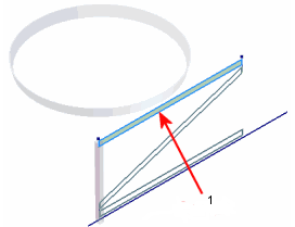
. Select the profile highlighted in the following illustration.
1 - Profile to select
- In the Extrude mini-toolbar, click the arrow next to the value input box containing the 10 mm default extrusion distance. Select List Parameters from the pop-up context menu. Click TubeSize in the Parameters list.
- Click the green Ok button to create the base feature.
- Add a 5 mm fillet to the four long edges of the new part.
- Click
3D Model tab
 Modify panel
 Shell
. Select the two end faces of the extrusion.
 - Click the arrow next to the Thickness edit box in the Shell dialog box, and select List Parameters from the pop-up context menu.
- Click TubeThickness in the Parameters list.
- Click OK.
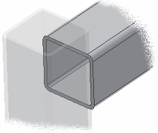
Your part should match the one shown in the following image.
 Note: With some additional work geometry in the skeleton model, you can create the end profile for the horizontal tube, like the vertical leg tube. It eliminates the need to add additional features to the part, but the additional complexity of the skeleton model may outweigh that advantage.
 - Return to the Frame subassembly.