Next, create a leg from the skeleton part and then ground it in the assembly.
- On the ribbon, click
Assemble tab
 Component panel
 Create
.
 - Enter Leg as the part name, and base the part on the Standard(mm).ipt template.
- Click OK in the Create In-Place Component dialog box.
- Expand the Origin folder under Skeleton.iam in the browser. Click the XY Plane node. It aligns the part origin to the assembly origin.Note: This step is critical to aligning all parts based on the skeleton model.
- Exit the sketch in the new part, and then delete Sketch1 to tidy up the Model browser.
- Use the Derive command to derive the SkeletonBase.ipt part into the Leg part.
- Exclude all sketches other than VERTICAL LEGS SKETCH.
- Expand Work Geometry in the Derived Part dialog box, and exclude all work features other than Work Plane-BOTT of Frame.
- Exclude Surface Bodies and Parameters from the derived component.
- Click OK.
- Click
3D Model tab
 Create panel
 Extrude
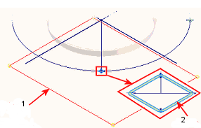
. Extrude the tube profile highlighted in the following illustration.
Extrude
. Extrude the tube profile highlighted in the following illustration.- Click the Extents button flyout arrow in the Extrude mini-toolbar, and select To selected face/point. Then, click the derived work plane in the graphics window.
- Click the green Ok button to complete the feature.

1 - Extrude to workplane
2 - Profile
- Expand SkeletonBase.ipt in the Model browser. Right-click Work Plane - BOTT of Frame, and remove the checkmark next to Visibility.
- Finally, return to the assembly environment. Right-click Leg in the Model browser and select Grounded from the pop-up context menu.
- Save the assembly.