- Expand Drawing Resources in the Model browser.
- Right-click Sketched Symbols and select Define New Symbol.
The drawing sketch environment is activated.
-
 On the ribbon, click Sketch tab
  Draw panel
  Text, and then click a location in the graphic window.
The Format Text dialog box is displayed.
- Review and keep the default text style. Then select _Piping Style from the Type list.
The Property list is populated with properties related to tube and pipe styles.
- Select Pipe Type from the Property list and click Add Text Parameter
 . The Pipe Type property is added to the text field.
 - Select Name from the Property list, and click Add Text Parameter to add the property to the text field.
- Add a hyphen (surrounded with two spaces) between the properties in the text field to separate the properties.
- Accept the other defaults and click OK to close the Format text dialog box.
A string with two selected piping style properties is previewed in the sketch.
- Right-click in the graphics window and select Done.
- Right-click again and select Save Sketched Symbol. Enter My Symbol in the Sketched Symbol dialog box, and click Save.
The new sketched symbol is added to the Sketched Symbol list in Drawing Resources.
-
 To place the symbol, click
Annotate tab
 Symbols panel
 User
.
 - Select My Symbol in the Symbols dialog box, and then click OK.
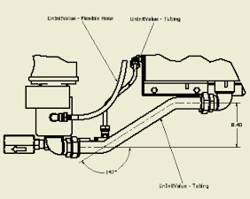
- Click an edge of a tube or pipe in the detail view, and click a point for the symbol leader. Then right-click and select Continue. A sketched symbol is placed in the drawing.
- Repeat the previous step for other tube or pipe parts. When finished, right-click and select Done.

- Save the drawing document.