The assembly is nearly complete. We will now finish placing the components necessary to create an accurate Bill of Materials and Parts List.
This section of the exercise assumes that you have Content Center installed and available. If Content Center is not available, the required hardware to finish the assembly is furnished in the tutorial directory. The steps listed in the following section do not detail the workflow to place the circlips without Content Center.
The Content Center allows you to place a component, adjust the size to match the target, and constrain it in a few picks. The target edge for the circlip we will place in the next section is the inside edge noted in the following image.
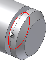
- On the
Assemble tab
 Component panel
, choose the drop-down arrow under Place to access the Place from Content Center command. You can also right-click in the graphics screen and select the command from the context menu.
 - Expand the section titled Shaft Parts.
- Expand the sub-section titled Circlips, and select External.
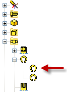
- Select ANSI B 27.7M in the dialog box, and then choose OK. A preview of the component appears in the graphics window attached to the cursor. The question mark in the preview image indicates that the clip can be automatically resized using AutoDrop.

- Move your cursor over the inside edge of the groove, and wait for the component to resize automatically. Click the edge when the component is the proper size, and then click the check mark in the AutoDrop dialog box to place and constrain the component.
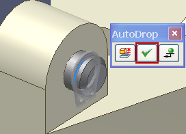
- Repeat to place the remaining circlips. Choose Done from the context menu when finished. There should be four instances of ANSI B 27.7N 3AMI-7 in the browser.
- Start the Place Component command.
- Place two copies of 6mm SHCS.ipt in the assembly.
- Rotate the components, if necessary, to position the hex opening up as shown in the following image.
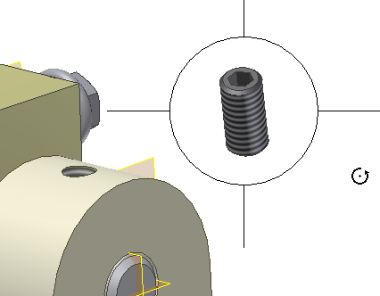
- Start the Constrain command, and place a Mate/Mate between the centerline of the fastener and the centerline of the hole.
- Choose Apply, and repeat for the other fastener. Click OK to apply the constraint and finish the command.
- Turn off the Visibility of the Cylinder Base.
- Start the Constrain command. Place a Mate/Mate constraint between the planar face at the bottom of the fastener and the planar face of the cutout in the lock pin.
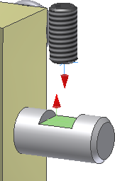
- Choose Apply and repeat for the other side.
- Choose OK to finish.
- Turn on the Visibility of the Cylinder Base.
- Save the file.