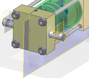
It is best to limit the number of constraints you use to position components. For example, if two components have face-to-face contact, then apply a single Mate constraint to the faces rather than using two Mate constraints on edges. Each constraint you add contributes to file size and complexity.
The following section details the steps to minimally and fully constrain cylindrical components in an assembly.
- Start the Place Component command.
- Place one copy of Long Shaft.ipt, and apply these constraints.
- Right-click, then choose Repeat Place and place one copy of Short Shaft.ipt. Right-click and select Done when finished.
-
 Start the Constrain command, and use Mate/Mate (the default) to constrain the axis of the long shaft to the axis of the lower hole.
 - Choose Apply to place the constraint.
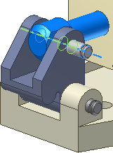
- Constrain the axis of the short shaft to the axis of the upper hole, as shown in the following image.
- Choose Apply to place the constraint.
-
 Change the constraint type to Mate/Flush.
 - Select the planar face of the base mounting tab first, and then select the planar face at the end of the long shaft. Enter 5 mm for the offset value. Notice that the face selection color matches the color of the selection arrow order. The first selection is blue and the second selection is green. This can help you troubleshoot constraints as you use Autodesk Inventor.
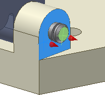 Note: If you pick the faces in the reverse order, enter a value of -5 mm.
 - Select Apply to place the constraint and stay in the dialog box to place another Mate/Flush constraint.
- Pick the planar face of the clamp, and then pick the planar face at the end of the short shaft. Enter an offset value of 4mm, and then click OK to finish the command.
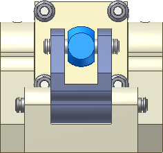
The long and short shafts should appear symmetrically constrained as shown in the following image. The shafts are still free to rotate, but the constraints that fix their position relative to the other components are in place.
In the next segment, we will place and position the two cylindrical lock pins. We will position them in the hole so the flat surface of the pin faces the tapped hole. In this case, we do not want the cylinder to rotate.
- Start the Place Component command, and place two instances of Lock Pin.ipt.
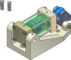
- Select the Cylinder Base component. Right-click, and select Visibility in the context menu to switch off the visibility .
- Place a Mate/Mate constraint to align each of the lock pins axially to the holes in the end of the Cylinder Body Sub_Assy. The long section should face towards the middle on both lock pins, with the flat area facing up as shown in the following image. Tip: Use the Rotate command to re-align the pins if they are constrained axially, but the long section is facing out. After rotating, use Update to recalculate the axial constraint in the new position.
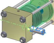
- Select the Cylinder Base in the browser. Right-click, and select Visibility to re-enable the component visibility.
To align the center of the flat area on the lock pin with the tapped hole in the base, we will create a work axis on the lock pin.
- Double-click one of the lock pin instances, or right-click and choose Edit Component from the marking menu to initiate an edit-in-place operation.
- On the
View tab
 Visibility panel
, select Object Visibility and ensure that All Workfeatures is enabled to view the work geometry.
 - On the
3D Model tab
 Work Features panel
, select Work Axis.
 - Select Work Plane1 and the XZ Plane in the Origin folder of the Lock Pin to create a Work Axis in the middle of the flat cutout. A work axis should appear in the center of the flat section, as shown in the following image.
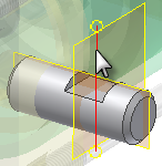
- Right-click, and choose Finish Edit from the marking menu. Alternatively, choose the Return command on the 3D Model tab to finish the local edit and return to the assembly.
- Start the Constrain command, and place a Mate/Mate constraint between the new work axis and the axis in the center of the tapped hole.
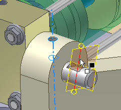
- Choose Apply to place the constraint.
- Place a Mate/Mate constraint between the two axes on the remaining lock pin to position the pin in the hole.
- Click OK to apply the constraint and exit the dialog box. The lock pins are fully constrained in alignment with the tapped holes.
- Save the file.
In the following image depicting the Cylinder Base, Enabled is toggled off, while Visibility is not. If a component is not enabled, it remains visible in a transparent state, but it is not selectable. A component that is not enabled appears green in the browser. To re-enable a component, select the component in the browser, and choose Enabled in the context menu.
