The Move Face command lets you move one or more faces on a part. You can specify an explicit direction and distance to move a set of faces. You can also freely move and rotate a set of faces or features about the X, Y, or Z axes using the Free Move option.
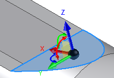
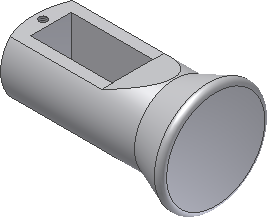
In this final section of the tutorial, the Free Move triad is used to modify the top angled face of the Sliding-pin Hanger.
-
 Click Model tab
 Modify panel
 Move Face on the ribbon.
 - Select the angled face on the top of the part. The Move Face Free Move triad appears.

You can interactively position a face or feature by dragging the triad in a planar move, axial move, or free movement. The selected area of the triad controls the movement. The colors help you identify triad axes:
- Red is the X axis
- Green is the Y axis
- Blue is the Z axis
When you first activate the triad, its origin sphere is coincident with the geometry you want to transform. Click a triad section or drag to indicate the type of transform you want. As you select other parts of the triad, you can drag or enter precise coordinates corresponding to your selection.
The triad is comprised of the following elements:
- Arrowheads move the triad along the axes.
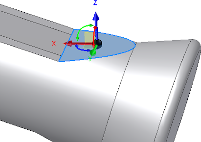
- Rotational manipulators rotate the triad around the axis. Click the red rotational manipulator to rotate in the YZ plane dynamically around the X axis. Click the green rotational manipulator to rotate dynamically in the XZ plane around the Y axis. Click the blue rotational manipulator to rotate dynamically in the XY plane around the Z axis.
- Planes move the triad in the selected plane.
- Sphere allows unrestricted movement in the view plane.
In the next step, we rotate the angled face in the XZ plane using the green rotational manipulator. It may be helpful to rotate the view a bit to provide easier access to the manipulator.
-
 Click the Free Orbit command in the Navigation Bar at the right of the graphics window. The rotation symbol appears in the graphics window with both vertical and horizontal axes. Click inside the rotation symbol. Press and hold the left mouse button as you move your cursor to approximate the viewing angle shown in the image.
  When you are satisfied with the new view, press the Esc key to exit the Free Orbit command. Tip: You can quickly access the Free Orbit function in the middle of another command by pressing and holding function key F4 as you rotate the view. When the view is rotated to your satisfaction, release the function key to resume the previous command. You can also use the ViewCube to orbit the model. Click and drag the cube to adjust your view.
- Click the green rotational manipulator and drag to the right to see the effects of a negative rotation. Drag to the left to view a positive rotation.
- Enter 2 in the value input box and click the green Ok button to rotate the face 2° in the positive direction.
The Move Face command terminates and the new feature, Move Face1, is added to the Model browser.
- Press F6 to restore the Home view.

- Save and close the file. This concludes the Introduction to Direct Manipulation tutorial.
Congratulations, you created your first Inventor part using Direct Manipulation!