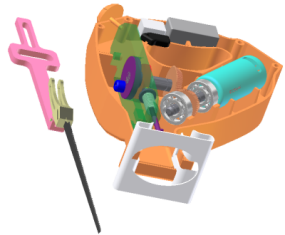
We will now complete the motion definitions so that the simulation reflects product operating conditions.
If the RecipSaw-tutorial_1.iam assembly is not open, open the file to continue. As you can see, although we have the saw body, we do not have the blade components. To add the blade components it is not necessary to leave the simulation environment.
Note: Make sure you are in Construction Mode before performing the next steps.
- Click the Assemble tab to display the Assembly ribbon.
- In the Component panel, click Place Component. Select Dynamic Simulation 1 and 2
 Blade set.iam and click Open.
 - Position the Blade set assembly near where it will be assembled.

- Right-click in the graphics window, and click Done.
- In the browser, expand the Blade set assembly node to display the components.
- Select the Scottish Yoke component. In the Quick Access toolbar, change the appearance to Chrome. Note: If you receive an Associative Design View Representation message about appearance associativity, select Remove associativity and click OK.
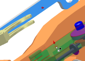
- Add a Mate constraint between the Scottish Yoke and the Guide to position the yoke on top of the guide.

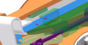
- Add a second Mate constraint between the two components to position the yoke within the guide rails. Notice that in the simulation browser, under Standard Joints, a prismatic joint was created based on adding those constraints.
