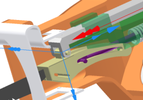
The mechanism thus far is lossless; meaning that it operates without friction or dampening as would normally be experienced. We will now add friction to capture the operating environment.
Add Friction and complete the yoke-guide relationship
- In the browser, right-click Blade set.iam, and click Flexible. By setting the assembly to Flexible, the assembly is placed into the welded group folder. Within that assembly, the constraints are evaluated and the constraint between the yoke and blade causes the addition of a Revolution joint.

- As previously mentioned, the assembly has no friction yet. This step imposes friction on the prismatic joint. Right-click the Prismatic Joint for the Guide and the Scottish Yoke, and click Properties.
- Click the dof 1 (T) tab.
- Click the Edit joint force command
 .
. - Click Enable joint force.
- Enter a Dry Friction coefficient of 0.1, and click OK.
- Now, you must add a constraint to position the Scottish Yoke with respect to the crank assembly. Exit the simulation environment and click the Assembly tab.
- Set the browser view to Model, and expand the Blade set.iam node.
- Expand the Scottish Yoke node, and click the Constrain command.
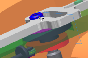
- In the browser, select Work Plane3 under the Scottish Yoke component.
- In the graphics window, select a circular edge of the Roller component that is part of the Crank cam assembly. A Point-Plane joint is added to reflect the constraint.

- Click OK to add the constraint and close the dialog box.
- Set the browser view back to Dynamic Simulation.
The resulting Point-Plane joint has five degrees of freedom and one constraint. It is enough definition to transfer motion without over constraining the model. Dynamic Simulation detects over-constrained conditions and helps you to resolve them.