Simplifying the model or part contributes to expediting the analysis. You can exclude parts whose purpose is simulated by a constraint and whose structural significance is otherwise small.
To help expedite analyses, you can suppress part features, such as rounds, that are either cosmetic or used to break sharp edges.
Exclude Components to Simplify Assemblies
Exclude a part or assembly from analysis:
- Expand the assembly browser nodes to the level where you see the component to exclude.
- Right-click the component and select Exclude From Simulation. Alternatively, right-click the component in the graphics region and click Exclude From Simulation.

The display of an excluded component changes to transparent while in the simulation environment.
Exclude Features to Simplify Parts and Assemblies
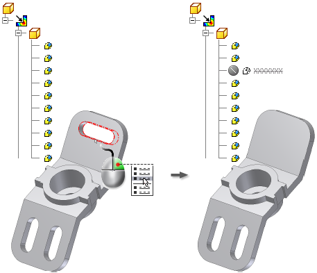
Suppressing features for analysis can speed up the meshing process. To exclude a part feature in the graphics window from your stress analysis:
- Change the select filter to Select Features
 .
. - In the graphics window, select features to exclude, either individually or with multi-select.
- Right-click and select Exclude From Simulation.
The features become invisible in the graphics window. In the browser, the features are unavailable and show with the Exclude icon ![]() . Dependent features are also made invisible and unavailable in the browser.
. Dependent features are also made invisible and unavailable in the browser.

Alternatively, you can select features in the browser to exclude:
- Expand the part browser node to the level where you see the features you want to exclude.
- Right-click the feature and select Exclude From Simulation.
If there is an error while creating the finite element mesh, an error dialog box displays. The potentially problematic geometry object highlights, and the mesh creation stops.
Analyze parts or assemblies containing thin wall bodies
To detect thin wall bodies, click Find Thin Bodies in the Prepare panel. If your model contain components that meet thin wall bodies criteria, a message box displays with an option to automatically create midsurfaces from detected thin wall bodies.
If you click OK, Midsurface dialog box opens. Click OK to evaluate the model and create midsurfaces. You can also click the Offset command to manually select face or faces to be analyzed for thin bodies criteria.
All midsurfaces and offsets are listed under Shells node in the browser.