Stretch selected geometry. Constraints associated with the selected geometry affect the stretch operation.
- Click
Sketch tab
 Modify panel
 Stretch
 . The Stretch dialog box opens with the Select command enabled.
 - In the graphics window, select the geometry, or select groups of geometry with the selection window. Right-click, and choose Continue to close the Select command, and activates Base Point in the Stretch dialog box. Tip: If you require only one geometry selection before center point selection, use Optimize for Single Selection. Then, the Base Point command is automatically active after you select the first geometry.
- Choose a method for defining the base point and endpoint of the stretch operation:
Stretch using the pointer
- To set the base point for the stretch operation, click in the graphics window . A dynamic preview displays dashed lines that represent the original geometry, and solid lines that represent the rotated geometry. The selected geometry stretches with the pointer at a constant offset that the base point selection establishes.
- Drag the pointer in the graphics window. It is not necessary to hold down the mouse button. As you move the pointer, the status bar shows its absolute sketch coordinates. The new position and shape update dynamically. Tip: As you drag the pointer to the approximate location, the endpoint snaps to the closest vertical or horizontal axis. To override this snap feature, hold down Ctrl while you drag, or in the Application Options
 Sketch tab, clear Snap to grid.
 - If constraints prevent the stretch operation, click More
 , and set overrides to relax dimensional constraints or break geometric constraints.
 - Click to set the endpoint. Tip: Click Backspace to reset the endpoint.
Stretch using precise input
- To open the Precise Input toolbar, select the Precise Input check box.
- Enter the coordinates for the base point, and press Enter. A dynamic preview displays dashed lines that represent the original geometry, and solid lines that represent the rotated geometry. The selected geometry stretches with the pointer at a constant offset that the base point selection establishes. The status bar shows the absolute sketch coordinates of the pointer.
- If constraints prevent the stretch operation, click More
 , and set overrides to relax dimensional constraints or break geometric constraints.
 - In the Precise Input toolbar, enter the endpoint coordinates, and press Enter. Tip: You can use the Precise Input toolbar to constrain the pointer movement to a specific X or Y value. For example, if you enter 6.5 in X, you can drag the pointer in the Y direction with X constrained to 6.5. Then you either enter a value in Y, or click in the graphics window to set the point.Tip: Click Backspace to reset the endpoint.
- Right-click, and select Done, click Done in the dialog box, or press Esc.
Stretch example
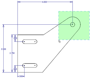
The Stretch command is active, and the two lines and the connecting arc are selected with the window selection method. 

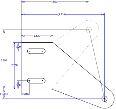
The geometry is selected in the graphics window, and the base point is selected in the Stretch dialog box. The geometry stretches to its new position. All necessary dimensions are relaxed. The original dimensions display normally, and the new dimensions display in parentheses. Only two of the dimensions are changed. Dotted lines indicate the original position of the geometry. 
