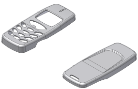
In this setion, you change the orientation of the Exp-Mobile Bottom part so it is consistent with the Exp-Mobile Top part.
In the General Mold Workflow tutorial you did not modify the orientation or position of the part. This mold assembly requires you to make some modifications. You use the Adjust Orientation command to modify the direction of a plastic part. The default direction of the mold opening does not align with the positive Z axis. You also ensure that the position of components is consistent. The Adjust Position command enables you to specify the position of plastic parts when there are multiple parts in a family mold.
- On the ribbon, click Mold Layout tab > Mold Layout panel > Adjust Orientation
 .
. - Ensure that the Plastic Part
 selector option is active .
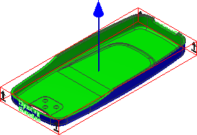
 - Select the Exp-Mobile Bottom.ipt part in the graphics window. The model displays the pull direction of the part, as shown in the following image. The orientation is not correct.
- Click Align with Axis
 .
. - Click Flip moldable part
 .
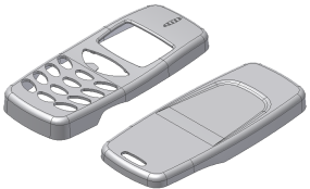
. - Click Done. The models appear as shown in the following image. The orientation is now correct.
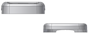
- Reorient the models to the Front view by using the ViewCube. Your model varies depending on how you placed the Exp-Mobile Bottom.ipt file. However, you must adjust the positioning of the two components relative to one another for the family mold, regardless of placement.
- Right-click in the graphics window and click Previous View to return to the previous 3D view of the mold assembly.
- On the ribbon, click Mold Layout tab > Mold Layout panel > Adjust Position
 . The Adjust Position command is in drop-down next to Adjust Orientation.
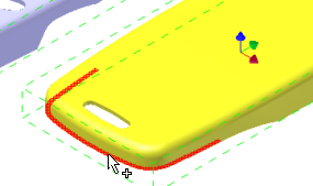
 - Ensure that the Plastic Part option is selected . Select the Exp-Mobile Bottom.ipt part, which turns yellow, and then select the surface highlighted in red in the following image.
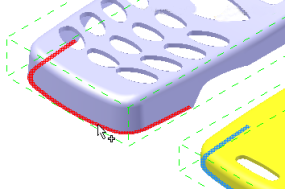
- Ensure that the Reference option is selected . Select the Exp-Mobile Top.ipt part, which retains its original color, and then select the surface highlighted in red in the following image.
- Reorient the models to the Front view by using the ViewCube. The models are like the following image.

- Adjust the X and Y offsets as follows:
- X Offset = 120
- Y Offset = 0
- Click OK. Right-click in the graphics window and click Previous View to return to the previous 3D view of the mold assembly. The mold assembly appears as shown in the following image.
