A tube and pipe assembly typically contains one or multiple individual runs within a tube and pipe runs subassembly. The number of runs you include depends on the complexity of the design and the documentation requirements for manufacturing drawings and parts lists.
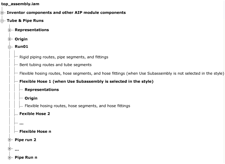
Rigid tubing and piping routes are directly embedded in a run but each flexible hose route is embedded in a flexible hose subassembly and then in a run. Each run can contain one or multiple rigid routes and flexible hose assemblies.
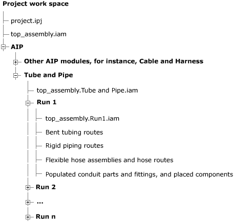
The following image illustrates a simplified default file structure on your local disk. Bold branches indicate a folder on your local disk containing single files. Normal branches indicate a file.

Compare the local file structure with the Model browser. The following image illustrates a simplified default structure of the Model browser. Bold branches indicate a folder container in the Model browser. Normal branches indicate route parts in the Model browser. No assembly configuration is illustrated in the image, but the Model browser structure also applies to a single assembly member.
