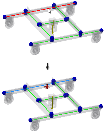
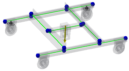
Next, we define the boundary conditions by adding structural constraints and loads. We start with constraints first.
Note: Constraints are required for frame simulations. If you start a simulation without constraints, a dialog box displays the error message: No constraints defined.
- In the Constraints panel, click Pinned
 . The dialog box displays with the Origin selector active.
 - Select the beam as shown in the image. The preview of the pinned constraint displays.

-
Make sure the Absolute option is selected in the Pinned Constraint dialog box. We insert the offset value using the absolute values measured from the beginning of the beam.
Note: You can use the Local Systems command in the Display panel to show the beam coordinate systems to define the beginning of the beams.
 - In the Pinned Constraint dialog box, set Offset to 170 mm, and click OK. The Pinned constraint is applied.
- Insert the second pinned constraint to the same beam. Again, click Pinned
 in the Constraints panel.
 - Select the same beam, and set Offset to 2330 mm. Click OK.
