In the next section, we allow Autodesk Inventor to place a plane in the middle of the part. This technique is useful because it does not require any dimensions or edits to maintain the position. If the width of the part is edited, the plane stays centered.
We will then create an offset work plane to use as the location of a new sketched feature.
-
 Select Midplane between Two Parallel Planes from the Plane drop-down menu. To create a work plane that bisects the part, pick the face with the new feature and then the parallel face on the opposite side of the part. A work plane is created in the middle of the part.
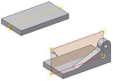
 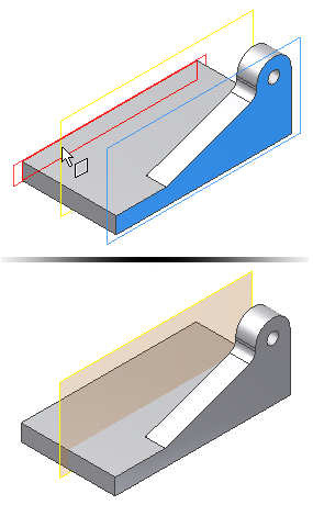 Note: The initial size of a work plane is determined by the size of the existing features. To resize a work plane, first select the corner, then drag the corner when the resize symbol appears.
-
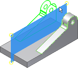
 Start the Mirror command. Select the extrusion, the fillet, and the through hole as the features to mirror.
 - When you finish selecting the features, choose the Mirror Plane selection arrow in the dialog box. You can also right-click and choose Continue from the context menu to change the selection arrow. Select the work plane in the center of the part to satisfy the Mirror Plane pick. Click the OK button to create the mirrored features and terminate the Mirror command.
-
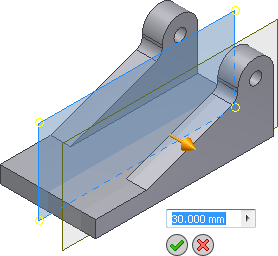
 Select Offset from Plane from the Plane drop-down menu.
 Steps 4-6 create a work plane that is parallel to the center plane and offset a specific distance.
- Select the center work plane, and drag the new work plane towards you using the distance arrow manipulator. The Offset value input box displays with a numeric value in it as you drag (if not, clear all selections and restart the command, then try again).
- Enter 30 mm in the Offset value input box to specify the exact distance from the center plane.
- Click the green check mark to finish the command.
-
 Start a new sketch on the offset work plane. (Select the edge of the work plane and click Create Sketch from the contextual mini-toolbar.) Note: When you select a work plane for a new sketch, no geometry is projected to “lock” the sketch to the part. Project model edges to obtain geometry for connecting the sketch.
 -
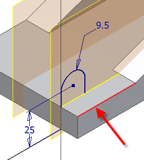
 Start the Project Geometry command. Select the front edge as shown to project it to the sketch plane, and then sketch and dimension the profile shown. Be sure to select the bottom edge of the part when creating the 25 mm dimension.
-
 Finish the sketch.
 -
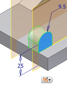
 Extrude the profile 14 mm towards the interior of the part. Use the Direction 2 button on the mini-toolbar to change the orientation before selecting OK.
-
 Start the Hole command.
 - Set the Placement option to Concentric.
- Select the plane and the concentric edge.
- Set the hole diameter to 8mm and the Termination to Through All
- Select OK to create the hole.
-
 Start the Mirror command. Select the extrusion and the through-hole as the features to mirror. Select the work plane in the center of the part to satisfy the Mirror Plane pick.
We now create two chamfers on the front of the base to create a smaller footprint for the front of the base. To determine the chamfer distance, we use the Measure Distance command to extract the distance between the two planes.
-
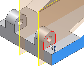
 Start the Measure Distance command. You will find this command in the marking menu, or on the Measure panel of the Tools tab. Select the plane on the outside of the part and the plane on the front face of the small mounting tab. The distance between the two faces displays as 13 mm. We will use this distance to create a chamfer that terminates at the edge of this feature and the edge of the mirrored copy.
-
 Start the Chamfer command. Select the Two Distances option from the fly-out button on the mini-toolbar.
- In the left value input box in the mini-toolbar, enter a value of 13 mm for Distance 1, and a value of 40 mm for Distance 2 in the right value input box. Click the Edges button and select the vertical edge on the outside of the part. If your preview image does not look like the preview in the following image, reverse the values for the distance input, or use the flip direction arrow to reverse the reference face.

- Click the green Apply button (+) to create the chamfer and stay in the Chamfer command. Select the opposite outside edge to create the second chamfer. Reverse the input values, or use the flip direction button to achieve the desired results.
In the next exercise, we create a tapped hole for a set screw on a curved face. To do this, we create a work plane that is tangent to the curve and parallel to the base.