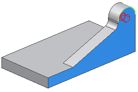
In the next step, there are multiple approaches to creating the feature:
- Create an extrusion the entire width of the part, and then cut out the middle.
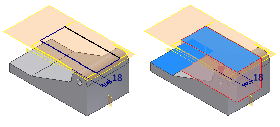
- Create an extrusion the exact depth and then mirror it:
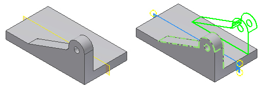
For this exercise, we detail the second technique.
-
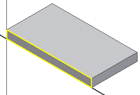
 Use Direct Manipulation to start a new sketch on the side of the part. Click the face indicated. When the mini-toolbar appears, select the third button on the right, Create Sketch.
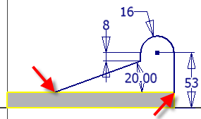
- Create and dimension the sketch profile geometry as shown. You do not have to draw the bottom horizontal line if you connect the line endpoints to the projected geometry. As you dimension the profile, keep in mind that the 53 mm dimension is from the bottom projected edge as shown in the image.
-
 Finish the sketch.
 -
 Extrude the profile 18 mm. Use the Direction 2 button on the mini-toolbar to extrude the profile to the interior of the part.
  Tip: The default direction for extrude/join is away from existing material. The default direction for extrude/cut is towards existing material. It is good idea to view a model in a 3D view before you extrude a profile to visualize the direction. If you make a mistake and extrude a profile to the wrong side, use Edit Feature and flip the direction.
 -
 Use Direct Manipulation to start the Fillet command. Click the edge indicated and select Create Fillet from the mini-toolbar. Drag the distance arrow manipulator to add an 8-mm radius to the edge, or enter 8 in the value input box.
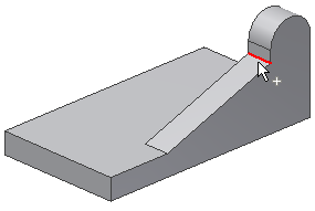
- Click the green check mark to finish the command.
-
 Start the Hole command.
 - Set the Placement option to Concentric.
- Select the plane and the concentric edge.
- Set the hole diameter to 11 mm and the Termination to Through All
