- Double-click Link Plate:1 in the browser.
- On the ribbon, click
3D Model tab
 Create panel
 Extrude
.
 - Select the Link Plate:1 sketch geometry as shown.
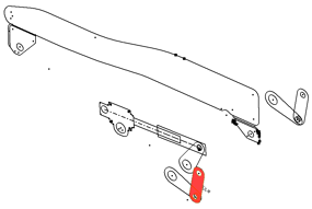
- Enter 3.5 mm for the extrude distance, and use the flip direction arrows to extrude in the negative Z direction.
- Click OK. Link Plate:2 is also updated to reflect the added feature.
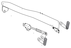
- Finish your edit of Link Plate:1.
- Double-click Pivot Plate:1, and repeat the steps necessary to extrude the pivot plates to a thickness of 3.5 mm.
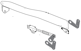
- Finish your edit of Pivot Plate:1, and save your file.
- As an exercise, add features to your other component instances to develop your assembly further.
-
After you create your component instances using Make Components, they remain associated to your layout. Changes to the shape of block instances are reflected in the corresponding components.
Activate Seat Adjust Layout.ipt. - Open Sketch1 for edit.
- Double-click Link Plate:1 in the browser. It opens the Link Plate sketch block for in-context edits.
- Change the dimension shown to 13 mm.
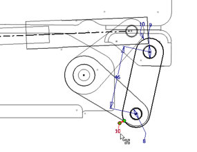
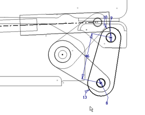
- Exit the block edit, and exit the sketch.
- Activate Seat Adjust Layout.iam.
- Click Update
 at the top of the window. Both Link Plate:1 and Link Plate:2 are updated to reflect the shape change in the Link Plate block definition.
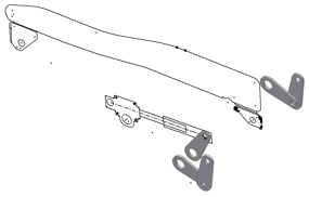
- Practice with other changes to your layout to demonstrate the power of associativity.
- Save your files.
The component instances you have derived establish the base geometry for your 3D components. After you have derived your components, your next step is to add features and further develop the component models. Here, you get started with a basic workflow.