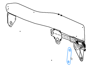
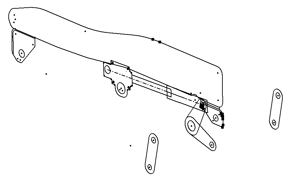
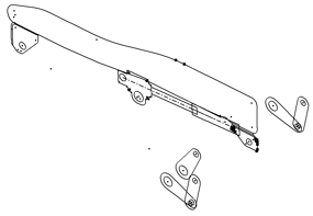
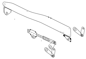
You can derive additional components from your layout into the same target assembly and you can position components at different Z axis locations.
- Go to Seat Adjust Layout.ipt.
- Edit Sketch1.
You will utilize Make Components from multiple blocks in the next steps. To use metric templates for each component, set the default templates on the Make Components Options dialog box.
- On the ribbon, click
Tools tab
 Options panel
 Document Settings
.
 - Under the Modeling tab, click Options in the Make Components Dialog area. In this dialog box, set the default part template to Standard (mm).ipt and the default assembly template to Standard (mm).iam. Use Browse to locate the metric templates.
- Click OK to exit the Make Components Options dialog box.
- Click OK to exit the Document Settings dialog box.
- Click
Sketch tab
 Layout panel
 Make Components
.
 - In the model browser, select Link Plate:1, Link Plate:2; Seat Pan:1, and Front Pivot Weldment:1.

- In the Make Components:Selection dialog box, ensure that the target assembly remains Seat Adjust Layout.iam, and click Next.
- Click OK. The graphics window changes to Seat Adjust Layout.iam.

Note the addition of the new components in the browser. Pause the cursor over the new components. Link Plate:1 and Link Plate:2 appear to be the same geometry because of their XY position. In subsequent steps, you differentiate the two components with an offset along the Z axis.
- The new files are not automatically saved after creation. Save Seat Adjust Layout.iam and associated components. Note: If your layout sketch is in edit mode, you are prompted to confirm that you want to exit edit mode and continue to save your files. Click OK.
- Click Seat Pan:1 and drag. Again, note that the seat kinematics are demonstrated.
- Undo the position changes to return the components to their default locations.
-
Currently, all components are constrained to the layout plane. Assume that the layout plane is the mid-plane of the seat. You can turn off Constrain to layout plane, move the components along the Z axis, then turn on Constrain to layout plane. The flush constraints will be re-enabled so that the components can only move parallel to the layout plane. However, now the constraints have an offset value that corresponds to their separation distance from the layout plane.
In the browser, expand Link Plate:1, and expand the Layout:2 constraint. - Right-click Link Plate:1, and select Layout Constraint. Turn off Constrain to layout plane. The XY Flush:2 constraint is suppressed and Z Angle:2 is enabled.
- Rotate your sketch to view the geometry off-plane.
- Click Link Plate:1, in the graphics window, and drag in the positive Z direction. It offsets the components from the layout plane.

- Turn Constrain to layout plane back on for Link Plate:1. XY Flush:2 is re-enabled and now shows an offset value.
- Click XY Flush:2.
- Enter a value of 120 mm in the entry box below the browser, and click Enter. The component is repositioned 120 mm from the layout plane, or mid-plane, of the seat.
- Perform the operations required to offset Link Plate:2 from the layout plane by 116.5 mm in the negative Z direction.

-
The pivot plate components in the Front Pivot Weldment:1 subassembly also must be offset from the layout plane. To access the components and constraints, first activate the assembly for edit.
In the browser, double-click Front Pivot Weldment:1. - Offset Pivot Plate:1 from the layout plane by 116.5 mm in the positive Z direction. This component is offset from Link Plate:1 by 3.5 mm to account for the link plate thickness. Note: The pivot plates may appear to float freely in the Y axis direction when they should be constrained by assembly constraints. It is because the assembly constraints are between Front Pivot Weldment:1 and other components. When you finish the edit of the Front Pivot Weldment:1, the pivot plate positions update according to the associated constraints.
- Offset Pivot Plate:3 from the layout plane by 113 mm in the negative Z direction.
- Offset Pivot Plate:2 from the layout plane by 84.25 mm in the positive Z direction.
- Finish the edit of Front Pivot Weldment:1.

- Offset Screw Rod Assy_Front:1 from the layout plane by 82.5 mm in the positive Z direction.

- Save your files.