In this section, you create the ejector pins to eject the plastic part. In a typical mold, the section attached to the fixed side of the press is referred to as the A side. The section attached to the moving side of the press is referred to as the B side.
Ejectors are pins or sleeves that push the plastic part out of the mold. Ejector pins are made of steel and are normally located on the B side of the mold. When the ejection system is activated, the pin pushes the plastic part or runner system out of the mold.
- On the ribbon, click Mold Assembly tab > Mold Assembly panel > Ejector
 .
. - Modify the d1 parameter value to 3 mm.
- Modify the L parameter value to 160 mm.
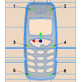
- Create six points in approximately the same locations as the points highlighted in the following image.

- Select the arrows in the bottom right-hand corner of the dialog box to expand and view the list of ejectors. Edit the X and Y coordinates as shown in the following table.
Ejector X Y EP1 14 mm 48 mm EP2 -14 mm 48 mm EP3 17 mm -7 mm EP4 -17 mm -7 mm EP5 15 mm -48 mm EP6 -15 mm -48 mm - On the Ejector: Mobile Top dialog box, select the Clearance tab.
- Change the clearance values for the ejector pins by entering the following values:
- CH = 7.0 mm
- CEP = 3.6 mm
- CB = 3.4 mm
- On the Ejector: Mobile Top dialog box, click Apply.
- Click OK in the File Naming dialog box to accept the defaults and create the ejector pins.
- From the Ejector: Mobile Top dialog box, select the Design tab and click Eject Runner System.
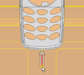
- Select the end point of the runner sketch, as shown in the following image.

- Click OK on the Ejector dialog box.
- Click OK on the file naming dialog box to create the ejector pin and close the dialog box.