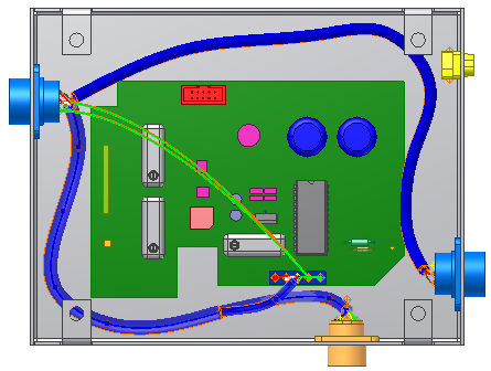
Create the splice at an arbitrary location, and then add two wires to the splice.
- Open Enclosure_Assembly.iam from the Cable & Harness subfolder. It is the same assembly you used in the previous tutorial.
- In the browser, double-click Harness Assembly1.
- Create a Generic 22AWG-GRN wire from U7 Pin 3 on Connector 360575:1 to J12 Pin 2 on LTP:1. Use the default Wire ID.
- Create another Generic 22AWG-GRN wire from U7 Pin 5 on connector 360575:1 to J12 Pin 2 on LTP:1. Use the default Wire ID and then click OK. The new wires are shown in the following image.

 On the ribbon, click
Cable and Harness tab
 Create panel
 Create Splice
.
Create Splice
.- On the Create Splice dialog box, leave the default values.
A green circle that represents the splice is attached to the cursor. A line representing the offset distance extends from the splice object.
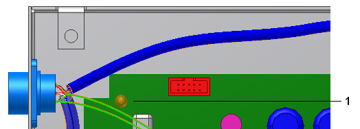
- Click in the graphics window near the location shown in the following image to place the splice. You move the splice later in the tutorial, so the exact location is not important.
The splice (1) is shown in the following image.
Note: To change the offset right-click again, select Edit Offset, and then enter a value. The default offset is set on the Splice tab of the Harness Settings dialog box.
- Click OK to create the splice.