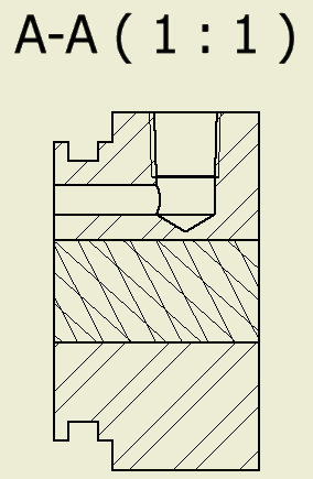
Some companies use custom hatch patterns to indicate a special material, surface finish, or to highlight an area for a manufacturing instruction. You can import AutoCAD standard pattern files into Inventor.
- Open the Style and Standard Editor and create a hatch style called Modified Hatch (ISO). On the Pattern dropdown list, select Other… . In the Select Hatch Pattern dialog box, select Load... In the Tutorial Files
 Cylinder Clamp folder, select Sample.pat, and click Open.
Two hatch patterns are available in that file- Sample1 and Sample2. Select Sample1, and click OK to close the Load Hatch Pattern dialog box. Click OK again to close the Select Hatch Pattern dialog box
Sample1 is now the active hatch pattern for this style. The image is a representation of the hatch pattern, but it is not a preview. The pattern lines are at an angle, and Angle reads 45 degrees.
- Change Angle to 0 degrees. The image does not update.
The Sample1 hatch pattern is defined with the crosshatch lines at 27 and 48 degree angles. The default Angle setting shifts the pattern by 45 degrees. By changing Angle to 0 degrees, the pattern appears in the drawing the way it was created.
Click Save, and click Done.
- Click View A-A.
On the Annotate tab, click Sketch Group
 Create Sketch. In the Draw group, click Project Geometry, and then select the four lines in the middle of the view. Click Done (ESC).
On the Sketch tab, in Draw group, click Fill/Hatch Region, and then click in the profile defined by the projected lines.
- In the Hatch/Color Fill dialog box, click the Hatch button to enable the hatch controls. In the Pattern list, select Sample1.
The pattern displays in the sketch. Although you selected the sample1 pattern, the rest of the settings did not update. The previous Angle setting does not work well with this pattern, so experiment with different angles.
In Angle, enter 90 degrees, and click OK.
The dialog box closes. Click Finish Sketch to return to the drawing. The section view resembles the following image.
 Note: Note If you do not select the view before you create the sketch, the sketch is created on the sheet instead of the view. You cannot project view geometry into a sheet sketch.