 |
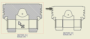
You can change the label, scale, display style, and other attributes of a drawing view. If appropriate, you can select a different design view representation to show component visibility and a positional representation to create a view from a kinematic "snapshot" of the assembly. |
Tips:
- To move a view, click and drag the red border of the view.
- You can delete a drawing view or copy and paste a view to another sheet. Right-click the view, and select the appropriate operation from the menu.
- If you need to recover work features after you have created a view, right-click the model in the browser, and then select Include Work Features. In the Include Work Features dialog box, specify the type of work features you want to recover in the drawing view.
- Default settings and values in the Drawing View dialog box are defined in the current standard and can be changed by using Style Editor.
Note: If you delete a view with dependent projected, section, detail, or auxiliary views, they are automatically deleted.
To edit a drawing view:
- In the graphics window or the browser, select the view.
- Right-click and select Edit View from the menu.
- In the Drawing View dialog box, on the Components tab, change the options related to the source model.
For assembly drawing views, you can also:
- Change an association of a view to a design view representation . Click the arrow to select a design view representation and select the Associative check box.
- If appropriate, select a different positional representation.
- For an iAssembly factory, select the member to represent in the view.
- Select a level of detail representation to improve view generation by using only unsuppressed components in the view.
- On the Model State tab, change the weldment state, reference options, or hidden line calculation options. Available options depend on the type of file used to create the view.
- On the Options tab, change attributes of reference data or display characteristics.
- Change the additional options:
- Select the view scale and edit the view identifier.
- Switch the visibility of the view label on or off.
- Click Edit View Label and edit the view label in the Format Text dialog box.
- Set the display style: Display or remove hidden lines and select shaded view, if appropriate. Note: If the Scale from Base or Style from Base option is selected, the scale or display style cannot be changed.
- Choose OK to close the Drawing View dialog box.
Suppress a drawing view
- Right-click a drawing view in the Model browser or in the graphic window.
- In the menu, select the Suppress option.
Note: To unsuppress a drawing view, right-click a drawing view in the Model browser, and unselect the Suppress option.
Tip: If you suppress several drawing views, it increases the performance of drawings created for large assemblies.
Control the cut inheritance for child views
You can control if child views inherit the section, slice, broken, or breakout cut.
- In the graphic window or the browser, select the child view.
- Right-click and select Edit View from the menu.
- On the Display Options tab of the Drawing View dialog box, select the appropriate check boxes in the Cut Inheritance section. The selected cuts are inherited from the parent view. Note: The available options depend on type of the edited view.
- Choose OK to close the Drawing View dialog box.
 Show Me how to use a bitmaps on shaded views to increase capacity and performance