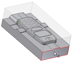
In the next three sections, you create inserts with heels that make up a slider assembly. The inserts are used to create an undercut on the part.
Inserts are individual pieces of metal in a mold base that are used to create a portion of the part. In this case, the insert is part of a slider. Inserts are added to an assembly by creating an insert or placing an existing insert.
You can create an insert by using a template, a shape, or a sketch:
- With the template method, an insert is created from one of the following predefined types: rectangular, square, circle, key1-flat, key2-flat, slot, or rounded rectangle. In this tutorial, you learn how to create an insert by using the template method.
- With the shape method, the profile of the insert is based on selected faces of the model. Only faces on the product, core, cavity, inserts, and core pins can be selected.
- With the sketch method, an existing sketch can be used as the profile for the insert. The sketch is created by using the Manual Sketch command, and the sketch must already exist in the model before this method can be used.
Click the following link to see how an insert is created by using the From Sketch method:
 Creating an insert using the From Sketch method
Click the following image to play an animation that shows creating an insert using the From Sketch method.
- On the ribbon, click Mold Layout tab > Mold Layout panel > Core/Cavity
 .
. - From the Core/Cavity tab, click Insert panel > Create Insert
 .
. - From the Create Insert dialog box, select Template in the Profile type menu. Maintain Rectangle as the Profile shape.
- Leave the Placement type as Linear. With a linear placement, you are required to select a plane and two linear references. The plane defines the surface on which the rectangular profile will be created. The references are selected edges that are used to locate the profile. To locate the profile correctly, Reference 1 and Reference 2 should be perpendicular to each other.
- The Plane
 selection tool automatically activates. Reorient the model and select the surface shown in the following image.
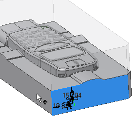
- The system prompts you to select Reference 1. Select the edge labeled 1 in the following image.
- The system prompts you to select Reference 2. Select the edge labeled 2 in the following image.

- On the Create Insert dialog box, ensure that the Select component
 tool is selected.
 - The Reference
 selection tool should be active . Select the core in the graphics window as the termination reference, as shown in the following image.
- In the upper-right corner of the graphics window, click Top on the ViewCube to orient the model.
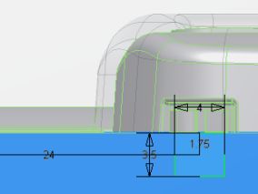
- Modify the following dimensions:
- Distance from Reference 1 = 1.75 mm
- Distance from Reference 2 = 24 mm
- Width of rectangle = 4 mm
- Height of rectangle = 3.5 mm
The sketch appears as shown in the following image.

- Click OK on the Create Insert dialog box.
- Click OK on the File Naming dialog box to accept the defaults and generate the insert.
- Reorient the model, as shown in the following image.
