When you select block instances for inclusion in a new sketch block, you create a nested block. You use sketch constraints, within the nested blocks, and the Flexible attribute to simulate kinematic subassemblies.
- Open Sketch1 for edit.
- Select the Worm Gear Assy:1 and Connecting Rod:1 block instances.

- Click Create Block.
- Enter Screw Rod Assy as the block name.
- Click OK. A new block definition Screw Rod Assy is created. Expand the block definition to view the nested structure.
- Expand the Screw Rod Assy:1 block instance in Sketch1. The Worm Gear Assy:2 and Connecting Rod:2 instances are dependents of the Screw Rod Assy block.
Note: When the Screw Rod Assy nested block is defined, the original instances Worm Gear Assy:1 and Connecting Rod:1 are deleted. New instances Worm Gear Assy:2 and Connecting Rod:2 are created as dependents in the nested block.
- Drag and drop the Screw Rod Assy block definition (from the Blocks folder) into the graphics window. The Screw Rod Assy:2 instance is created.

- Double-click either Screw Rod Assy instance in the Model browser. The block definition is open for in-context edit. All other geometry is shaded to gray.

- Double-click the Worm Gear Assy:2 block instance, either in the Model browser or in the graphics window.
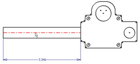
- Create a centerline down the axis of the Worm Gear Assy, as shown. Ensure that the centerline endpoints are constrained to the Worm Gear Assy geometry. This centerline will participate in a collinear constraint with the centerline of the Connecting Rod.
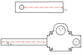
 Note: Both instances of the Worm Gear Assy update to show the centerline.
 - Right-click, and select Finish Edit Block. You are returned to the edit of the Screw Rod Assy block.Note: Alternatively, you can double-click the Screw Rod Assy block instance node to finish the edit of the Worm Gear Assy block. This returns you to the edit of the Screw Rod Assy block.
- Apply the collinear constraint between the Worm Gear Assy and Connecting Rod centerlines.

- Right-click, and select Show All Constraints. The collinear constraint glyphs are shown for both Screw Rod Assy instances.

- Right-click, and select Hide All Constraints.
- Click the Connecting Rod geometry in the graphics window and drag. The sketch block instances begin to demonstrate basic kinematics due to the collinear constraint.


- Right-click, and select Finish Edit Block.Note: Alternatively, you can double-click the Sketch1 browser node to finish editing the block and return to the sketch.
Use sketch constraints between nested blocks to represent your assembly.
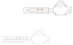
- Select Screw Rod Assy:2, and use Rotate on the Sketch tab to rotate as shown.

- Apply the Coincident constraint
 to the block instances as shown.

- Click the corner geometry of either block instance in the graphics window and drag.

Since the block instances are constrained at the sketch level, you can move the block instances relative to one another. However, the geometry within the block instances shows no relative motion. To manipulate the block instance degrees of freedom outside of the block instances, you toggle the block instance to Flexible.
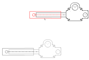
- Right-click each Screw Rod Assy instance, and check Flexible.
- Click different sections of the block instance geometry, and drag to see the effect.
-
Experiment with different constraints, both within the block instances and at the sketch level, and note how you can simulate different kinematics. You begin to see the power behind nested and flexible sketch blocks.
- Exit the sketch and drag the geometry. With the block instances toggled to Flexible, the degrees of freedom remain exposed at the part level.
- Save your part file and exit. The tutorial is complete.