In this task you will learn how part geometry and analysis technologies affect analysis results.
Using 3D analysis technology for thin-walled parts produces comparable results to using Dual Domain analysis technology, but requires more computational resources and time to run the analysis. 3D results of a thick or complex part are more accurate than Dual Domain for the same part.
The following part looks shell-like in nature, indicating that Dual Domain analysis technology may be appropriate. However, physical examination of the part is not always a reliable indication of which analysis technology is appropriate.
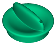
Cavity side view.
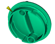
Core side view.

Locking grooves.
A Fill analysis on the Dual Domain model does not adequately represent the thickness variation in the model, which leads to a poor flow front prediction. The gate location makes the problem worse because the flow is not symmetrical along the axis of the part. The more complicated flow towards the end of fill is not predicted with a Dual Domain analysis.
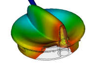
Fill analysis on a Dual Domain model.
A Fill analysis on the 3D model, which analyzes through the thickness of the part, accurately predicts the formation of a weld line. The weld line was caused by the uneven flow of material around the internal boss, which was not accurately represented in the Dual Domain analysis.
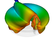
Fill analysis on a 3D model.
Below is a picture showing a short shot of the actual part, which mirrors that predicted by 3D analysis technology. The start of the formation of a weld line is apparent. This is an area of weakness in the part.
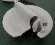
Knob short shot showing weld lines starting to form
Parts are often a combination of thin sections and complicated features. To ensure the most appropriate analysis technology is used, select the Check Suitability option when importing the part and use the recommended analysis.
Redesigning the slides that create the locking grooves to allow the injection location to be in line with the handle would result in a more symmetrical flow. This would prevent the weld line from forming. Unfortunately, such tool redesign may not be possible.
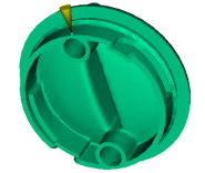
Relocated injection location.
In this example, the injection location could not be changed due to tool constraints, so the thickness of small sections of the part were altered to make the flow front more symmetrical and eliminate the problem weld line. 3D analysis technology was used to accurately represent the flow around the complex features and thickness changes in the part.
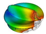
Improved fill pattern, 3D analysis technology.