Investigate how Dual Domain and 3D analysis technologies differ when modeling the part and how this affects analysis results.
The following demonstration model is used to compare the two analysis technologies. It is a thick part that is best analyzed using the 3D analysis technology. The part will also be analyzed with Dual Domain analysis technology (which is inappropriate for this part), to illustrate the different approaches used by each analysis technology.
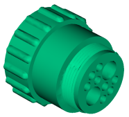
Round connector.
To investigate the model, a cutting plane was used to investigate the Fill time result.
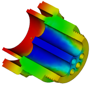
3D representation.
The volume of the part is represented by 3D analysis technology. You can see the graduated result through the thickness of the part.
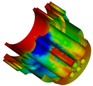
Dual Domain representation.
The shell of the part is represented with Dual Domain analysis technology, which only displays results on the surface of the part. You can not see a graduated result through the thick areas. Because this is a thick part, 3D analysis technology produces more accurate results.
The progressive filling of the part further highlights the differences.
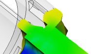
Partial Fill-3D.
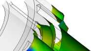
Partial Fill-Dual Domain.
Dual Domain analysis technology assumes that the plastic flow between the surfaces of the part is laminar. When the part is thin and shell-like, 3D analysis technology and Dual Domain analysis technology produce similar results.
Complex shapes, thick ribs, holes, thick corners, etc., can cause the flow front to be misrepresented by Dual Domain analysis technology. In these cases, using 3D analysis technology will produce more accurate results because of the way the internal geometry of the part is represented and analyzed.