The Warpage indicator, differential cooling result highlights those areas of the part where the out-of-plane deflections attributable to these differential cooling effects are approaching or exceeding the specified nominal maximum deflection (NMD) value.
One of the three contributors to warpage is shrinkage variations due to differential mold temperatures on each side of the component.
Using this result
The colors displayed in this plot are based on the following assessment criteria.
| Color(Assessment) | Explanation |
|---|---|
| Green (Low) | The out-of-plane deflections are less than 80 percent of the specified NMD value. The contribution of differential cooling effects to the warpage is low. |
| Yellow (Medium) | The out-of-plane deflections are between 80 percent and 120 percent of the specified NMD. The contribution of differential cooling effects to the warpage is significant. You should consider taking measures to reduce differential cooling in this area. |
| Red (High) | The out-of-plane deflections are greater than 120 percent of the specified NMD. Differential cooling effects are a key contributor to the warpage and corrective measures need to be taken. |
Things to look for
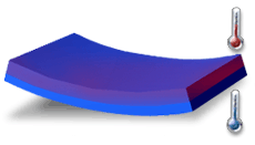
Shrinkage due to differential temperature typically results in the bowing of the part, as shown in the figure below. This type of shrinkage is usually due to poor cooling system design.

While the part is in the mold, temperature differences from one side of the mold to the other cause variations in shrinkage through the thickness of the component. In addition to this, any temperature differences at ejection will cause further warpage as both sides of the part cool to room temperature.
What to do next
-
Changing cooling line layout.
-
Using mold inserts.
One of the easiest things to alter is the coolant temperature. It may be useful to run two additional Cool analyses with the coolant inlet temperatures at, for example, plus and minus 10°F (5°C) with respect to the original inlet temperature used. The results from the Cool analyses can then give you some idea of the sensitivity of the part to variations in coolant temperature.
If it is not sufficient to simply alter the coolant temperature, you can consider the addition of extra cooling lines in troublesome regions or the use of mold inserts to reduce variations in cooling rates across the part.