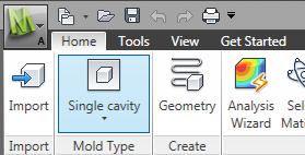
- Select
 ( Home tab > Mold Type panel > Single Cavity).
- Click
 (Home tab > Create panel > Geometry).
 - Click
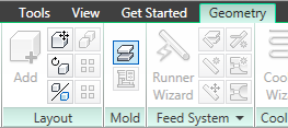
 (Geometry tab > Mold panel > Set Parting Plane) to open the Set parting plane dialog.
The model is displayed with the mold outline and a red line and square grab handles across the model. This line represents the parting plane. - Ensure the Display Grid and Snap to grid check-boxes in the Grid settings box are selected.
- Click Bottom then Apply. The parting plane has been automatically set at the bottom of the cavity and an outline of the proposed mold is displayed.
- Click Close to close the Set parting plane dialog.