When a structure is loaded up incrementally, it is quite likely that at a certain level of load, the configuration of the structure will start to alter considerably faster than before.
This can easily be recognized on the associated load-deflection path, as a section where there is a definite change of slope and/or curvature. Normally such a change will be of the softening type, that is, the slope decreases and the displacements grow more rapidly than before, accompanied by a noticeable alteration in shape. Such behavior is referred to by the general term buckling. Buckling falls into two main types, namely, the buckling of perfect and imperfect structures respectively.
Buckling of Perfect Structures
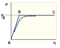
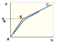
As the load increases, a perfect structure initially follows its primary (or fundamental) equilibrium path, AB in GUID-3175C968-B186-4A50-954F-CC60B5E1575F.htm#FIG_8464070BF6C6414B8672A81A21BE9588, GUID-3175C968-B186-4A50-954F-CC60B5E1575F.htm#FIGURE1B and GUID-3175C968-B186-4A50-954F-CC60B5E1575F.htm#FIG_65E525BE99F2437CB5FE358A531CA4A5. During this stage, the stiffness of the structure with respect to its weakest direction (that is, lateral or out-of-plane direction) is being steadily degraded. At point B, called a bifurcation point, the structure buckles by following the (current) line of least resistance. This form of buckling can be viewed as the transition from a stiff membrane (axial) dominated path to a flexible bending dominated path. Because slender beams and thin-walled plates and shells are much stiffer axially than flexurally, it is natural that they are the most prone to buckling.
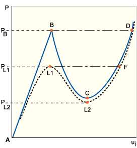
The paths BC in GUID-3175C968-B186-4A50-954F-CC60B5E1575F.htm#FIG_8464070BF6C6414B8672A81A21BE9588, GUID-3175C968-B186-4A50-954F-CC60B5E1575F.htm#FIGURE1B and GUID-3175C968-B186-4A50-954F-CC60B5E1575F.htm#FIG_65E525BE99F2437CB5FE358A531CA4A5 are called the secondary or postbuckling paths. The stability of the structure following bifurcation is characterized by the slope of the secondary path at B. Thus, the equilibrium states at B are neutral (GUID-3175C968-B186-4A50-954F-CC60B5E1575F.htm#FIG_8464070BF6C6414B8672A81A21BE9588), stable (GUID-3175C968-B186-4A50-954F-CC60B5E1575F.htm#FIGURE1B) and unstable (GUID-3175C968-B186-4A50-954F-CC60B5E1575F.htm#FIG_65E525BE99F2437CB5FE358A531CA4A5).
In the unstable case, any arbitrarily small increase in load will cause the structure to jump instantaneously through to an adjacent stable equilibrium configuration (for example, the chain dotted path BD in GUID-3175C968-B186-4A50-954F-CC60B5E1575F.htm#FIG_65E525BE99F2437CB5FE358A531CA4A5). This phenomenon is called snap-through buckling. Note that the alternative postbuckling path, depicted by the solid curved path BCD in GUID-3175C968-B186-4A50-954F-CC60B5E1575F.htm#FIG_65E525BE99F2437CB5FE358A531CA4A5, traces the theoretical equilibrium states that would occur if snap-through is prevented, and load is progressively removed until a stable path is regained at point C.
Stability and buckling: straight column
Stability and buckling: flat plate
Stability and buckling: cylindrical shell
Obviously, from a designer's point of view, a stable postbuckling path is desirable and, provided displacements remain acceptable, it is not unusual to utilize the increase in postbuckling strength that is available. On the other hand, an unstable equilibrium path will rarely be acceptable, particularly as it will normally be accompanied by dynamic snap-through. Furthermore, structures that exhibit unstable buckling are often imperfection sensitive, that is, the maximum or critical load capacity is sensitive to quite small changes in the magnitude and shape of initial imperfections.
Buckling of Imperfect Structures
A real structure can never be perfect. Even minor disturbances of geometry, loading, boundary conditions or material properties will usually prevent true bifurcations from occurring. Instead of the primary and secondary paths intersecting to form a slope discontinuity, both paths curve locally to form one continuous and unique solution. The resulting postbuckling path is depicted by the dotted lines in GUID-3175C968-B186-4A50-954F-CC60B5E1575F.htm#FIG_8464070BF6C6414B8672A81A21BE9588, GUID-3175C968-B186-4A50-954F-CC60B5E1575F.htm#FIGURE1B and GUID-3175C968-B186-4A50-954F-CC60B5E1575F.htm#FIG_65E525BE99F2437CB5FE358A531CA4A5. As the magnitude of the imperfections decreases, the more localized will the change of curvature become. Where the perfect structure would exhibit an unstable bifurcation point, the imperfect structure exhibits a limit point (point L1 in GUID-3175C968-B186-4A50-954F-CC60B5E1575F.htm#FIG_65E525BE99F2437CB5FE358A531CA4A5).

Further along the postbuckling path we may encounter a second limit point but this time it will be a minimum on the load-deflection curve (point L2 in GUID-3175C968-B186-4A50-954F-CC60B5E1575F.htm#FIG_65E525BE99F2437CB5FE358A531CA4A5). Note that, analogous to the perfect structure, the unstable path L1L2 will not actually be followed. Instead, instantaneous snap-through buckling depicted by the chain-dotted path L1F will occur. Although buckling of a perfect structure normally involves bifurcation, this is by no means always the case. Instead, unstable buckling via a limit point can occur whenever the prebuckling mode shape contains symmetries that cannot be broken because of the imposed boundary conditions. For this reason bifurcation buckling is sometimes referred to as symmetry breaking.
Analysis Considerations
When carrying out a non-linear incremental analysis of a perfect structure that contains symmetries, it is necessary to assign a small imperfection to the structure in order to break the symmetry. If this is not done, the solution is likely to continue along the fundamental equilibrium path instead of branching onto the true postbuckling path. Examples where this may occur are a straight column under co-axial load and a flat plate under in-plane load. The latter example can be realized when performing Warp analysis on a flat part with no Cool analysis results. The recommended procedure in such a case is to build in a small geometrical imperfection whose shape corresponds to the expected buckling mode shape. (If the buckling mode shape is not known, then any out-of-plane shape can be used.)