In this task, you will use the Mesh editing tools to eliminate the Free Edges indicated in the Mesh Statistics dialog.
- Ensure the Tutorial 3 project you created in Task 1 is open.
- Click
 then
then  and import the file tutorial_free_edges.sdy from the Tutorial folder, typically C:\Program Files\Autodesk\Simulation Moldflow Insight 20xx\tutorial
 - Click
 () .
() . - Select the Place results in diagnostics layer checkbox.
- Click Show , and then click Close.
- In the Layers pane, right-click on Diagnostic results and select Hide All Other Layers . Three groups of problem elements consisting of nine free edges are present.
- Click
 Expand Layer from the top of the Layers panel, accept the defaults, and click OK.
 - Enter the values 40 -25 -5 in the Rotation Angle text box
 (), and press Enter to rotate the model.
 - Click
 (). The model should appear as shown in the following image.
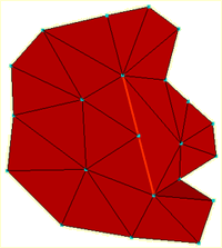
Three edges need stitching, one for each of the adjacent triangles. There is a very fine gap between the triangles that cannot be detected visually.
- Click
 ()
() - Click and drag a rectangle around the three nodes that lie along the red line and click Apply. The edges are stitched.
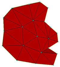
Notice how the largest adjacent triangle has been split into two smaller elements in the process.
- Press
 (Next) on the Diagnostic Navigator panel ().
You can also hold down the Ctrl key and select individual nodes along the edge instead of dragging a rectangle around the free edges.
- The Stitch Free Edges tool pane should still be open. With the Ctrl key held down, click on the nodes along the free edge and then click Apply.
- Click
 () and rotate the model to
40 -140 -55
.
() and rotate the model to
40 -140 -55
.
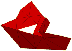
It is not appropriate to stitch this triangle. Instead you could use the Fill Hole or Create Triangles as you did in an earlier task. You will use Create Triangles in this instance.
- Click
 ().
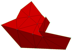
(). - Select Automatically apply when selection complete. When three appropriate nodes are selected, the triangle will be generated without the need to click the Apply button.
- Select the three corner nodes of the hole. The element is added to the model automatically.
- Click
 to verify that all free edges have been removed.
Click the Next topic link below to move on to the next task of the tutorial.