In this task you will complete steps to fix intersecting elements.
In this task, you will:
- Use two different techniques to repair intersecting elements.
- Use a transparent layer to help view the model.
- Review the Mesh Statistics after repairing a mesh.
Intersecting mesh elements are triangles that touch each other at locations other than edges and nodes. You need to fix intersecting elements before attempting to analyze your model. These errors are reported in the Mesh Statistics dialog.
Fix Intersecting Elements-Delete and Fill
- Ensure the Tutorial 3 project you created in Task 1 is open.
- Click
 () and import the file base_mesh.sdy from the Tutorial folder, typically C:\Program Files\Autodesk\Simulation Moldflow Insight 20xx\tutorial.
 - Click
 () to open the Mesh tab.
 - Click
 ().
().
Note there are 2 Fully overlapping elements . Click Close.
- Click
 ().
(). - Select Place results in diagnostics layer.
- Click Show , and then click Close.
- In the Layers pane, right-click the Diagnostic results layer and select Hide All Other Layers.
- Click
 Expand Layer, accept the default, and click OK.
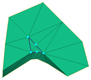
Two pairs of intersecting elements should now be visible.
To help visualize where these overlaps occur within the model, you will now create a transparent layer.
- Select the New Triangles checkbox in the Layers panel.
- Click
 Layer Display from the toolbar across the top of the Layers panel.
 - Select Transparent from the Show as drop-down list and click Close.
- Enter the values -155 145 -75 in the Rotation Angles text box
 , and press Enter to rotate the model.
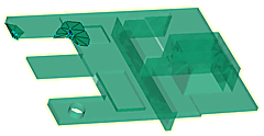
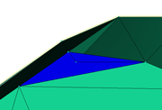
- Uncheck the New Triangles layer and zoom in on the large group of elements.
- Click
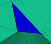
 from the Mesh Repair panel drop-down menu.
 - Select the blue element. Click Apply. The small underlying element that is now apparent is also part of the problem and needs to be deleted.

- Select the second small element.
- Click Apply.

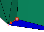
- Click
 .
. - Select the nodes along the long edge of the hole as illustrated below.
- Click Apply.
A node has been inserted along the selected edge and the adjacent element was modified.
- Click
 .
. - Select a node along the edge of the hole. Click Search and a blue line appears around the hole.
- Click Apply and the hole is filled.
You could have filled the mesh without adding a node along the long edge of the hole, but you would have introduced a high aspect ratio element in the process.
- Click
 .
. - Enter -5 155 35 into the Rotation Angle textbox to rotate the model.
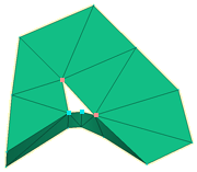
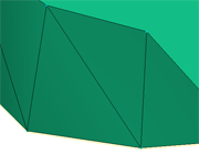
Deleting the overlapping elements and filling the resulting hole would introduce a jagged edge to the curved surface as shown below.

To remove overlap without causing this jagged edge, you will merge nodes. This will maintain the smoother profile.
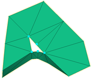
- Rotate the model to -155 155 -45.
We will eliminate the short edge of the highlighted element by merging the inner node to the outer edge of the model.
- Click
 .
. - Select the node on the outer edge of the model. Note how the node number for this element has been entered in the Node to merge to text box in the Tools panel.
- Select the inner node and note how this node number is entered in the Nodes to merge from text box.
- Click Apply. Rotate the model to ensure the profile is appropriate.
- Click .
All elements with intersection problems have been eliminated. Some of the new elements we have created have generated an Elements not oriented error.
- Click Close on the Mesh Statistic dialog.
- Select the New Triangles layer and click
 Front using the ViewCube.
 - Click
 to show the whole model.
 - Click
 , and click Show.
The elements that need orienting are highlighted.
- Click
 from the Mesh Repair panel drop-down menu.
The mesh has now been repaired. Check the mesh statistics to confirm this.
Click the Next topic link below to move on to the next task of the tutorial.